
This section briefly reviews the menus and commands in order to understand the basic purpose of each.
The toolbar is displayed across the top of the application window, below the menu bar. The toolbar provides quick mouse access to many tools used in Global Mapper. To hide or display the toolbars or to switch to the old Toolbar display, which some users prefer, use the View menu commands for the toolbar.
Menu HeadingsThe File menu offers the following commands:

The Open Data File(s) command allows the user to open additional data files into the main Global Mapper view. If no other data is already loaded and the user has not explicitly set a projection, the view will adopt the projection and datum of the first data file selected for loading. If other data is already loaded, the selected data files will be displayed in the current projection/datum.
Note: Global Mapper automatically opens files with tar.gz extensions without the use of a decompression tool such as Winzip. This is particularly useful for SDTS transfers, which are typically distributed in a .tar.gz format.
Open Generic ASCII Text File(s) CommandThe Open Generic ASCII Text File(s) command allows the user to import data from a wide variety of generic ASCII text formats.
Selecting the Open Generic ASCII Text File command prompts the user to select the file(s) to load and then displays the Generic ASCII Text Import Options dialog (pictured below). This dialog allows the user to specify how the text file(s) are formatted so that they can be imported.
Global Mapper supports coordinates in decimal format as well as degree/minute and degree/minute/second coordinates.
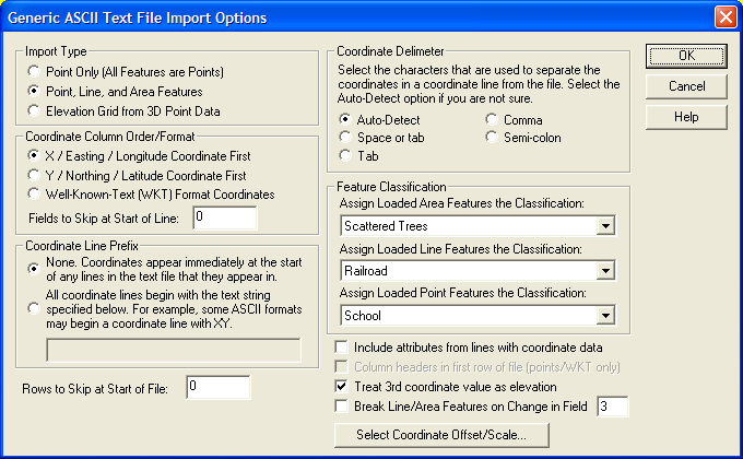
The Import Type section allows the user to specify how they want the data in the file to be treated. The different import types are defined as follows:
The Coordinate Column Order section allows the user to specify in what order the coordinates are found on coordinate lines in the file. Coordinates can either be x followed by y (i.e. longitude then latitude) or the reverse. Elevation values, if any, are always assumed to come after the x and y values. The Fields to Skip at Start of Line setting controls what field index (column) the coordinates start in. For example, if the x and y coordinates are in the 3rd and 4th columns, set this value to 2 so that the coordinates will be grabbed from the appropriate place.
The Coordinate Delimeter section allows the user to specify what character the coordinates are separated by on coordinate lines. If the Auto-Detect option is selected, Global Mapper will attempt to automatically determine the coordinate delimeter. This option will usually work and should probably be used unless you have trouble.
The Coordinate Line Prefix section allows the user to specify whether coordinates start at the beginning of the line or if coordinate lines start with some other sequence of characters. For example, some formats may start coordinate lines with the sequence "XY,".
The Rows to Skip at Start of File setting controls how many lines to skip at the start of the file before trying to extract data. This is useful if you have some header lines at the start of your file that you want to skip over.
The Feature Classification section allows the user to specify what feature type to assign to area, line, and point features imported from the file.
If the Include attributes from lines with coordinate data option is selected, any text found AFTER the coordinate data on a line from the file will be including as attribute for the feature that coordinate is in. If not selected, only lines from the file that are not determined to contain coordinate data will be used as attributes.
If you are doing a Point Only import and the Column Headers in First Row of File option is checked, values in the first line from the file will be used at the names of attributes for attributes found in coordinate data lines. This is useful for things like CSV files.
If the Treat 3rd coordinate value as elevation option is selected and a numeric value is found immediately following the x and y (or lat and lon) coordinate values, that value will be treated as an elevation. Otherwise, the value will be included as an attribute if the Include attributes from lines with coordinate data option is selected. Typically you want to leave this option checked unless you are importing point data in which the 3rd column is an attribute that occasionally contains all numeric values, such as well names.
If you have line and/or area data that do not have non-coordinate lines separating them but rather are delimited by a change in a particular field/column of data, you can use the Break Line/Area Features on Change in Field option to specify which field (use a 1-based index) to check for breaking the data into separate line/area features.
Pressing the Select Coordinate Offset/Scale button displays a dialog that allows the user to select an offset and scale factor to apply to each coordinate. The offset entered will first be added to each coordinate, and then each coordinate will be multiplied by the scale factor.
When generic ASCII text files are imported, Global Mapper will scan the attributes associated with each feature and look for any attribute names that are known to it. The following is an abbreviated list of attribute names that are currently recognized by Global Mapper when generic ASCII text files are read (see the links below the list for more complete lists):
Click here for more instructions on creating generic ASCII data files with features of various types and click here for more documentation on the supported fields.
The Download Online Imagery/Topo/Terrain Maps command allows the user to download mapping data from numerous built-in and user-supplied sources. This includes premium access to high resolution color imagery for the entire world from DigitalGlobe, worldwide street maps from OpenStreetMap.org, as well as seamless USGS topographic maps and satellite imagery for the entire United States from MSRMaps.com/TerraServer-USA. In addition, access is provided to several built-in WMS (OpenGC Web Map Server) databases to provide easy access to digitial terrain data (NED and SRTM) as well as color satellite imagery (Landsat7) for the entire world. You can also add your own WMS data sources for access to any data published on a WMS server.
This is an extremely powerful feature as it puts many terabytes of usually very expensive data right at your fingertips in Global Mapper for no additional cost (with the exception of access to the un-watermarked DigitalGlobe imagery, which is not free). Note that this feature requires Internet access to work.
When you select the menu command, the Select Online Data Source to Download dialog (pictured below) is displayed. This dialog allows you to select the type, or theme, of data to download, as well as the extents of the data to download. You can either select to download the current screen bounds, an area to download around an address, specify a lat/lon bounds explicitly, or select to download the entire data source.

Once the data to download is defined, Global Mapper will automatically download the most appropriate layer for display as you zoom in and out. This way, you can see an overview of the data when zoomed out, with more detail becoming available when you zoom in. You can also export this data in full resolution to any of the supported raster export formats, such as GeoTIFF, JPG, or ECW. The most appropriate detail level for the export sample spacing will be used to obtain the source data for the export.
Each data source load will appear as a separate layer in the Overlay Control Center. Each entry can have it's display options modified just like any other raster layer to drape it over elevation data, blend it with other layers, etc.
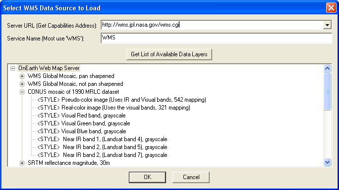
You can use the Add WMS Data Source button to display the Select WMS Data Source to Load dialog (pictured below). This dialog allows you to specify the URL of a WMS data source and select what layer(s) to add as an available data source on the Select Online Data Source to Download dialog. The URL that you should specify is the GetCapabilities URL, such as http://wms.jpl.nasa.gov/wms.cgi for the JPL WMS data server (a great source of data, like Blue Marble imagery). Once you've entered the URL, press the Get List of Available Data Layers button to query the server and populate the data control with the available data layers on that server. Then simply select the data layer and style that you want and press OK to have it added to the available data source list. Once a source is added, you can use the Remove Source button to remove it from the list of available data sources at a later time. If you need to specify additional options for the WMS server, such as forcing a particular image format to be used, add those parameters after the Service Name parameter. For example, to force the use of the JPG format, you might specify a Service Name parameter of 'WMS&format=image/jpeg'.
You can also use the Delete Cached Files button to remove any locally cached files from any particular type of data sources. This is useful if the online data may have changed or if you have downloaded corrupt files somehow.
The Add Sources From File button allows you to add new WMS sources from an external text file. This provides an easy way to share your list of WMS sources with other users. You can simply provide them with your wms_user_sources.txt file from your Application Data folder (see the Help->About dialog for the location of this folder) and they can load that file with this button to add their sources to your source list.
The Open All Files in a Directory Tree command allows the user to open all of the files matching a user-specified filename mask under a user-selected directory. You will first be prompted to select a folder from which to load the files. After selecting the folder, you will be prompted to enter a filename mask for all of the files that you would like to attempt to load. After selecting a filename mask, all files under the selected folder which match the filename mask and are recognized by Global Mapper as a known data type will be loaded.
The filename mask supports the * and ? wildcard characters. The default mask of * will check all files under the selected folder. You can also cause data to only be loaded from selected folders as well. For example, if you had a large collection of folders with data split up into 1x1 degree blocks with the folder names depecting the 1x1 degree block they held, you could use a directory name mask to load only those blocks that you wanted. For example, you might use a mask of N4?W10?\*.tif to load all TIFF files between N40 and N50 and W110 and W100.
You can also specify multiple masks if you need more than one to describe the set of files that you would like to load. Simply separate the masks with a space.
Open ECW File from the Web CommandThe Open ECW File from the Web command allows the user to open an ER Mapper Compressed Wavelet (ECW) image file directly from an Image Web Server URL. While these files may be terabytes in actual size, only the portion needed for the current display window is downloaded, allowing for the browsing of extremely large data sets.
Selecting the Open ECW File from the Web command displays the Load Image From Web dialog (pictured below). This dialog allows the user to either select a predefined web link for loading or to enter the URL of any available ECW file served by Image Web Server.
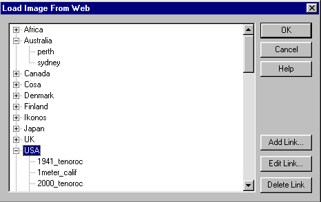
The tree on the left of the dialog allows the user to select which data file they wish to load. Global Mapper comes with several dozen useful links already entered into the tree.
To access your own ECW image from the web, press the Add Link... button. This button causes the Add New Web Link dialog (pictured below) to be displayed.
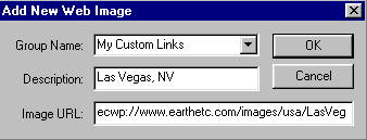
The Group Name drop list allows the user to select which group, if any, to place the new link in. Any of the predefined groups can be selected, or a new group name can be entered. Leaving the group name blank will cause the new link to appear at the root level of the tree.
The Description field is where you enter the human-readable description of the link. This is what will be displayed for the link on the main dialog. Leaving this blank will cause the URL to be displayed instead.
The URL field is the most important piece of this dialog. This is where you specify the address of the ECW file to load. The URL should begin with the prefix ecwp:// with the remainder being a valid path to an ECW file served using ER Mapper's Image Web Server software.
When you've completed entering information about the new web link, press the OK button to complete your entry and have it added to the web link tree in the Load Image From Web dialog.
Pressing the Edit Link... button allows the user to edit the currently selected web link. Note that the built-in web links cannot be edited.
Pressing the Delete Link... button will delete the currently selected web link or group from the web link tree.
If you get an error message indicating that your settings have been updated to support the ECWP protocol whenever you try to load an ECW layer from the web you need to download and install the latest ECW ActiveX plugin from http://demo.ermapper.com/ecwplugins/DownloadIEPlugin.htm.
Open Data File at Fixed Screen LocationThe Open Data File at Fixed Screen Location command allows the user to open any supported data file format for display at a fixed location on the screen rather than at a fixed location on the earth. This is particularly useful for loading things like bitmaps for legends and logos. The loaded data will be used for screen display, export, and printing operations.
Selecting the Open Data File at Fixed Screen Location command first prompts you to select a file to load, then displays the Fixed Screen Location Setup dialog (pictured below). This dialog allows the user to specify the size and position of the data relative to the screen/export/printout.

The Unload All command unloads all overlays and clears the screen.
Create New Map Catalog CommandThe Create New Map Catalog command allows you to create a "map catalog". A "map catalog" is a collection of map files which are grouped together to allow for easy loading, viewing, and export. Layers in a map catalog will be loaded and unloaded as needed for display and export, potentially greatly reducing the load time and memory requirements for working with very large collections of data.
Upon selecting this command and selecting the file to save the map catalog to, the Modify Map Catalog dialog (shown below) will be displayed, allowing you to add files to the catalog, control at what zoom level data layers are loaded for display, and setup how the map bounding boxes are displayed when you are zoomed out too far for the actual map data to display. By default map bounding boxes are displayed using the style set for the Map Catalog Layer Bounds type.
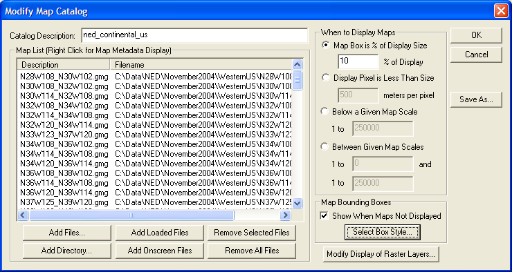
You can obtain metadata and projection information about layers in the map catalog by right-clicking on them in the Map List and selecting the appropriate option.
You can modify map catalogs again after loading them by opening the Overlay Control Center, selecting the map catalog layer, then pressing the Options button.
Note: Only registered users of Global Mapper are able to create map catalogs.
Load Workspace CommandThe Load Workspace command allows the user to load a Global Mapper workspace file (.gsw) previously saved with the Save Workspace command.
Note: Only registered users of Global Mapper are able to load Global Mapper workspace files.
Save Workspace CommandThe Save Workspace command allows the user to save their current set of loaded overlays to a Global Mapper workspace file for later loading with the Load Workspace command.
The Global Mapper workspace maintains the list of all currently loaded overlays as well as some state information about each of those overlays. When the workspace file is loaded, all of the overlays that were loaded at the time the workspace file was saved will be loaded into Global Mapper. This provides a handy way to easily load a group of overlays which you work with often.
The Global Mapper workspace will also contain any changes that you have made to loaded vector features as well as any new vector features that you have created. The user projection and last view on the data will also be maintained.
Find Data Online CommandSelecting the Find Data Online command will open a web browser pointing to places on the internet where data compatible with Global Mapper is available for download.
Run Script CommandThe Run Script command allows users to run a Global Mapper script file that they have created. This is a powerful option that allows the user to automate a wide variety of tasks. Click here for a guide to the scripting language.
Selecting the Run Script command from the menu displays the Script Processing dialog, shown here.
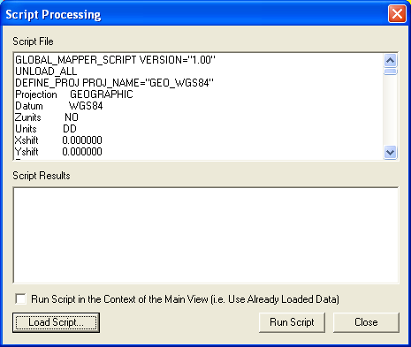
The Script File pane displays the currently loaded script file. To load a new script file for processing, press the Load Script... button at the bottom left corner of the dialog.
If you would like the script file to make use of data already loaded in the main view and to also affect what is displayed in the main view, check the Run Script in the Context of the Main View option prior to running the script.
To run the loaded script file, press the Run Script button. Any warning, error, or status messages generated while running the script will be output to the Script Results pane.
When you are done processing scripts, press the Cancel button to close the dialog.
Note: Only registered users of Global Mapper are able to run Global Mapper script files.
Capture Screen Contents to Image CommandThe Capture Screen Contents to Image command allows user to save the current contents of the Global Mapper window to a JPEG, PNG, (Geo)TIFF, or Windows Bitmap (BMP) file. In addition, the generated image can be generated in a higher resolution than the screen to provide greater fidelity. Also, a world file for georeferencing in other software packages as well as a projection (PRJ) file describing the native ground reference system of the image can be optionally generated as well.
Unlike the raster export commands described later, the Capture Screen Contents to Image command also saves any vector overlays drawn to the screen.
Selecting the Capture Screen Contents to Image command from the menu displays the Screen Capture Options dialog, shown here.
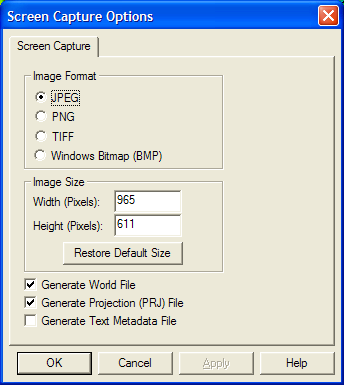
The Image Format section allows the user to select the format of the image to generate. Different formats have their own unique strenghts and weaknesses which make choosing the best format vary depending on the desired end results. The supported formats are:
The width and height of the generated image in pixels are specified in the Image Size panel. By default, the size of the Global Mapper view pane are used. Using these values will generate an image that exactly matches what you see. You can change these values to generate a more or less resolute image with the obvious tradeoff of size vs. quality.
Checking the Generate World File option results in a world file being generated in addition to the image. The world file will be generated in the same directory as the image and will have the same primary name as the image. The filename extension will depend on the selected image type (JPEG=.jpgw, PNG=.pngw, TIFF=.tfw,BMP=.bmpw).
Checking the Generate Projection (PRJ) File option results in a projection file being generated describing the ground reference system of the created image. The projection file will be generated in the same directory as the image and will have the same primary name as the image with an extension of .prj.
Checking the Generate Text Metadata File option results in a text file being generated listing the metadata for the captured image.
Pressing the OK button prompts the user to select the name and location of the image to generate and then proceeds to generate the image.
Note: Only registered users of Global Mapper are able capture the screen to an image file.
Export Global Mapper Package File CommandThe Export Global Mapper Package File command allows the user to export any or all of the loaded data to a Global Mapper package file. These files are similar to workspace files except that the actual data is stored in the files. Package files provide an easy way to pass around lots of data between Global Mapper users on different computers with a single self-contained file.
When selected, the command displays the Global Mapper Package Export Options dialog which allows the user to setup the package export. The dialog consists of a Package Options panel, a Simplification panel, a Gridding panel, and an Export Bounds panel.
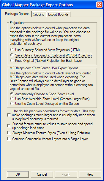
The Package Options panel consists of options allowing the user to select the projection to save the data in, how to handle dynamically streamed MSRMaps.com/TerraServer-USA data, and other options. These include the Always Maintain Feature Styles option, which specifies that any vector features stored in the package file should explicitly save the styling of that feature, even if they are using the default style for the feature classification. This can make it easier to maintain exact styling when transferring packages between Global Mapper installations.
In the Projection section of the panel, the user can choose to save all loaded data in the currently selected view projection (this is the projection selected on the Projection tab of the Configuration dialog), in latitude/longitude coordinates (the "Geographic" projection) with the WGS84 datum, or to keep each layer in its original native projection.
In the TerraServer Export Options section of the panel, the user can select how displayed layers from the Download TerraServer menu option are exported. The Automatic selection for imagery themes (i.e. DOQs, Urban Area imagery) will save data slightly more detailed than what is displayed on the screen. For the DRG (topographic map) theme, the most detailed zoom range for the current scale of DRG map being displayed (i.e. 24K, 100K, 250K) will be determined and data from that scale will be saved. The other alternatives either save the most detailed scale available, creating potentially very large files, or the scale the most closely matches the current display scale on the screen.
The Combine Compatible Vector Layers into a Single Layer option causes all vector features with the same native projection to be combined into a single layer within the package file rather than maintaining their original layer structure.
The Simplification panel allows the user to set up the threshold at which points that don't contribute much to the shape of the vector line and area features being exported are removed in order to generate features with less vertices. By default, all vertices will be kept, but the user can move the slider to the right to get rid of relatively insignificant vertices and realize significant space spacings at the cost of some fidelity.
The Gridding panel allows the user to split up the data into regularly spaced tiles on export if desired rather than just exporting a single file.
The Export Bounds panel allows the user to select what portion of the loaded data they wish to export.
Note: Only registered users of Global Mapper are able capture the screen to an image file.
Export PDF/GeoPDF File CommandThe Export PDF File command allows the user to export any or all of the loaded data to a Geo-enabled PDF file. These are standard PDF files that can be read in Adobe Acrobat Reader. They also will have geopositioning information embedded in them so that mapping applications like Global Mapper can automatically display the data in the PDF at the proper location.
When selected, the command displays the PDF Export Options dialog which allows the user to setup the PDF export. The dialog consists of a PDF Options panel, a Gridding panel, and an Export Bounds panel.
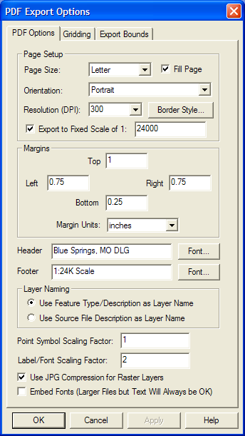
The PDF Options tab allows the user to setup the PDF-specific export options. The following sections are available:
The Gridding panel allows the user to split up the data into regularly spaced tiles on export if desired rather than just exporting a single file.
The Export Bounds panel allows the user to select what portion of the loaded data they wish to export.
Note: Only registered users of Global Mapper are able capture the screen to an image file.
Export Raster and Elevation DataThe commands on the Export Raster and Elevation Data submenu allow the user to export loaded raster and elevation data to various formats.
Export Arc ASCII Grid CommandThe Export Arc ASCII Grid command allows the user to export any loaded elevation grid data sets to an Arc ASCII Grid format file.
When selected, the command displays the Arc ASCII Grid Export Options dialog which allows the user to setup the export. The dialog consists of a General options panel which allows the user to set up the grid spacing and vertical units, a Gridding panel and an Export Bounds panel which allows the user to set up the portion of the loaded data they wish to export.
Note: Only registered users of Global Mapper are able to export data to any format.
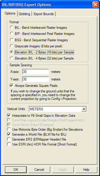
Export BIL/BIP/BSQ CommandThe Export BIL/BIP/BSQ command allows the user to export any loaded raster, vector, and/or elevation grid data to a BIL, BIP, or BSQ format file.
When selected, the command displays the BIL/BIP/BSQ Export Options dialog which allows the user to setup the export. The dialog consists of an Options panel (pictured below), which allows the user to set up type of export to perform, the sample spacing, vertical units, and other applicable options, a Gridding Panel, and an Export Bounds panel which allows the user to set up the portion of the loaded data they wish to export.
Note: Only registered users of Global Mapper are able to export data to any format.
Export BMP CommandThe Export BMP command allows the user to export any loaded raster, vector, and elevation grid data sets to a 24-bit RGB BMP file.
When selected, the command displays the BMP Export Options dialog which allows the user to setup the export. The dialog consists of a General options panel which allows the user to set up the pixel spacing, a Gridding panel, and an Export Bounds panel which allows the user to set up the portion of the loaded data they wish to export.
Note: Only registered users of Global Mapper are able to export data to any format.
Export BT (Binary Terrain) CommandThe Export BT (Binary Terrain) command allows the user to export any loaded elevation grid data sets to a BT (Binary Terrain) format file.
When selected, the command displays the BT (Binary Terrain) Export Options dialog which allows the user to setup the export. The dialog consists of a General options panel which allows the user to set up the grid spacing to use, a Gridding panel, and an Export Bounds panel which allows the user to set up the portion of the loaded data they wish to export.
Note: Only registered users of Global Mapper are able to export data to any format.
Export DEM CommandThe Export DEM command allows the user to export any loaded elevation grid data sets to a native format USGS DEM file.
When selected, the command displays the DEM Export Options dialog which allows the user to setup the export. The dialog consists of a General options panel which allows the user to set up the quadrangle name, grid spacing and vertical units, a Gridding panel, and an Export Bounds panel which allows the user to set up the portion of the loaded data they wish to export.
Note: Only registered users of Global Mapper are able to export data to any format.
Export DTED CommandThe Export DTED command allows the user to export any loaded elevation grid data sets to native format DTED files. DTED files support a set of fixed resolutions (i.e. DTED levels) which are defined as aligning on particular boundaries. When you select the DTED level to export to and the export bounds, this defines which DTED tiles need to be generated to conform to the DTED standards for that level. The filename that you select for the export is used as a base, with the lat/lon coordinates of the southwest corner of each tile appended to each filename as it is exported.
When selected, the command displays the DTED Export Options dialog which allows the user to setup the export. The dialog consists of a DTED Options panel which allows the user to set up the DTED level and other options, a Gridding panel, and an Export Bounds panel which allows the user to set up the portion of the loaded data they wish to export.
ADVANCED USERS: You can change the accuracy value exported in DTED files by specifying your own string value (up to 4 characters in length) at "HKEY_CURRENT_USER\Software\Global Mapper\DTEDAccuracy". The collection system value (up to 12 characters in length) can be specified at "HKEY_CURRENT_USER\Software\Global Mapper\DTEDCollectionSystem".
Note: Only registered users of Global Mapper are able to export data to any format.
Export DXF 3D Face File CommandThe Export DXF 3D Face File command allows the user to export any loaded gridded elevation data sets to a DXF 3D Face file.
When selected, the command displays the DXF 3D Face Export Options dialog which allows the user to setup the export. The dialog consists of a General options panel which allows the user to set up the grid spacing and vertical units, a Gridding panel, and an Export Bounds panel which allows the user to set up the portion of the loaded data they wish to export.
Note: Only registered users of Global Mapper are able to export data to any format.
Export DXF Mesh CommandThe Export DXF Mesh command allows the user to export any loaded elevation grid data sets to a 3D DXF Mesh file.
When selected, the command displays the DXF Mesh Export Options dialog which allows the user to setup the export. The dialog consists of a General options panel which allows the user to set up the grid spacing and vertical units, a Gridding panel, and an Export Bounds panel which allows the user to set up the portion of the loaded data they wish to export.
Note: Only registered users of Global Mapper are able to export data to any format.
Export DXF Point CommandThe Export DXF Point command allows the user to export any loaded elevation grid data sets to a 3D DXF Point file. The DXF file will consist of a 3D DXF point for each point in the elevation grid defined by the spacing and extents that the user specifies. This option may be useful when used with other software packages that do not specify the DXF mesh format.
When selected, the command displays the 3D DXF Point Export Options dialog which allows the user to setup the export. The dialog consists of a General options panel which allows the user to set up the grid spacing and vertical units, a Gridding panel, and an Export Bounds panel which allows the user to set up the portion of the loaded data they wish to export.
Note: Only registered users of Global Mapper are able to export data to any format.
Export ECW CommandThe Export ECW command allows the user to export any loaded raster, vector, and elevation grid data sets to an ECW file. ECW files are highly compressed and great for storing things like satellite imagery. There is no size restriction on exported ECW files, so you can store many terabytes worth of imagery within a single highly compressed ECW file.
When selected, the command displays the ECW Export Options dialog which allows the user to setup the export. The dialog consists of a General options panel which allows the user to set up the pixel spacing and target compression ration, a Gridding panel, and an Export Bounds panel which allows the user to set up the portion of the loaded data they wish to export. If you would like to generate a lossless JPG2000 format file, simply slide the Target Compression Ratio slider all the way to the right (1:1 target compression ration).
Note: Only registered users of Global Mapper are able to export data to any format.
Export Erdas Imagine CommandThe Export Erdas Imagine command allows the user to export any loaded raster, vector,and elevation grid data sets to an Erdas Imagine file.
When selected, the command displays the Erdas Imagine Export Options dialog which allows the user to setup the export. The dialog consists of a General options panel which allows the user to set up the pixel spacing and format, a Gridding panel, and an Export Bounds panel which allows the user to set up the portion of the loaded data they wish to export.
Note: Only registered users of Global Mapper are able to export data to any format.
Export Float/Grid CommandThe Export Float/Grid command allows the user to export any loaded elevation grid data sets to a Float/Grid format file. The Float/Grid file will consist of a 4-byte IEEE floating point number for each elevation sample in the file, starting at the top-left corner and proceeding across, then down. In addition to the elevation data file, an ESRI-format .hdr file and .prj file will also be generated. There is also an option to allow exporting slope values (in degrees) or slope directions (in bearings where 0 is north, 90 is east, etc.) rather than elevation values at each sample location.
When selected, the command displays the Float/Grid Point Export Options dialog which allows the user to setup the export. The dialog consists of a General options panel which allows the user to set up the grid spacing and vertical units, a Gridding panel, and an Export Bounds panel which allows the user to set up the portion of the loaded data they wish to export.
Note: Only registered users of Global Mapper are able to export data to any format.
Export Geosoft Grid CommandThe Export Geosoft Grid command allows the user to export any loaded elevation grid data sets to a Geosoft Binary Grid format file.
When selected, the command displays the Geosoft Grid Export Options dialog which allows the user to setup the export. The dialog consists of a General options panel which allows the user to set up the grid spacing to use, a Gridding panel, and an Export Bounds panel which allows the user to set up the portion of the loaded data they wish to export.
Note: Only registered users of Global Mapper are able to export data to any format.
Export GeoTIFF CommandThe Export GeoTIFF command allows the user to export any loaded raster, vector, and elevation data sets to a GeoTIFF format file.
When selected, the command displays the GeoTIFF Export Options dialog (pictured below) which allows the user to set up the export. The dialog consists of a GeoTIFF Options panel, a Gridding panel, and an Export Bounds panel which allows the user to set up the portion of the loaded vector data they wish to export.

The File Type section allows you to choose what type of GeoTIFF file to generate. The various file types are described below:
When generating a 256 color (8-bits per pixel) GeoTIFF, it is necessary to select a palette indicates what 256 colors will be used to describe the image being exported. The following choices of palette are available:
The Vertical Units field allows the user to select the vertical units to use when exporting elevation data (i.e. meters or feet). Any input data not in the selected vertical units will be automatically converted on export.
The Resolution section allows the user to selected the grid spacing to use when generating the GeoTIFF. The default value is the average of the grid spacings of all the currently loaded raster and elevation overlays. If the Always Generate Square Pixels option is checked, the smaller of the specified x and y resolutions will be used for both the x and y resolution. Forcing square pixels ensures that the resultant GeoTIFF file will look good even in software that is not able to deal with pixels that aren't square. If you'd like to specify the spacing in units other than those of the currently selected view/export projection, press the Click Here to Calculate Spacing in Other Units button.
If you want to generate a GeoTIFF file corresponding to a particular scale relative to the selected DPI value (see below), you can check the Export at the Fixed Scale option and then specify the scale to use. For example, if you specify a scale value of 25000, each inch in the output (an inch being the number of pixels equal to the specified DPI value) will be approximately equivalent to 25,000 inches on the ground.
The DPI Value to Save in Image option allows you to specify a DPI (dots per inch) value to save in the TIFF header. Some software, in particular graphics editing software, makes use of this value when sizing TIFF files for printout. Specifying the default value of 0 will result in the DPI tag not being saved to the TIFF file at all.
The Compression selection allows you to select what type of compression to use for the selected export file type. The available compression types are as follows:
If the Make Background (Void) Pixels Transparent option is checked for 8-bit palette, 24-bit RGB, or JPEG-in-TIFF files, an alpha channel will be added to the created GeoTIFF file to indicate which pixels should be treated as transparent. Note that this will create a larger file and not all applications will support TIFF files with alpha channels.
If the ADVANCED: Use Tile Rather than Strip Orientation option is checked, the GeoTIFF file will use a tile-based organization rather than a strip/scanline-based orientation. A tile-based orientation has advantages when zoomed in on a layer for display, but can be slower when zoomed further out. By default a tile size of 128x128 will be used, but you can customize this by creating a DWORD registry key value 'HKEY_CURRENT_USER\Software\Global Mapper\GeoTIFFExport_TileSize' with the desired tile size (like 256 for example for 256x256 tiles).
If the Save Scale/Elevation Legend/Grid if Displayed option is checked, the distance scale, elevation legend, and coordinate grid will be saved to the GeoTIFF file (except vertical GeoTIFFs) if they are configured to show up in the main display.
If the Save Vector Data if Displayed option is checked, any loaded vector data that is configured to show up in the main display will be saved to the GeoTIFF file (except vertical GeoTIFFs).
If the Generate TFW File option is checked a TIFF world file will be generated with the same name as the GeoTIFF file with a .tfw extension. The TFW file is used by software that is not capable of reading the placement of the GeoTIFF file directly from the GeoTIFF header.
If the Interpolate to Fill Small Gaps in Data option is checked, any small areas with missing data will be filled in by interpolating the surrounding valid data. This is useful for filling small gaps between adjacent tiles or small holes in elevation data.
If the Generate PRJ File option is checked a describing the projection of the coordinates in the file will automatically be created
Export Global Mapper Grid CommandThe Export Global Mapper Grid command allows the user to export any loaded elevation grid data sets to a Global Mapper Grid format file. The Global Mapper Grid format is a highly compressed elevation grid format that loads and draws very quickly and requires very little memory. If you have a choice for what format to store your gridded elevation data in, we suggest using the Global Mapper Grid format.
When selected, the command displays the Global Mapper Grid Export Options dialog which allows the user to setup the export. The dialog consists of a General options panel which allows the user to set up the grid spacing and vertical units, a Gridding panel, and an Export Bounds panel which allows the user to set up the portion of the loaded data they wish to export.
Note: Only registered users of Global Mapper are able to export data to any format.
Export Google Maps Tiles CommandThe Export Google Maps Tiles command allows the user to export any loaded datato JPG or PNG files tiled in the configuration required for display in using the Google Maps interface. This command will create both the image tiles and a sample HTML file for displaying the data with the Google Maps interface. You can just load the HTML file into your web browser to view the data once the export is over. You can also customize the HTML file however you need to.
When you select the command, the Google Maps Export Options dialog (pictured below) appears allowing you to setup the export. This dialog allows you to specify the display name of the map set in your web browser, the zoom level setup, the Google Maps API key to use, the format of the imagery, and some additional options. There is also an Export Bounds panel which allows the user to set up the portion of the loaded data they wish to export.
Note: Users without a permanent registration key that export Google Maps tiles will get a large diagonal DEMO symbol across the image. Registered users will not see that symbol on their output.
Export Gravsoft Grid CommandThe Export Gravsoft Grid command allows the user to export any loaded elevation grid data sets to a Gravsoft Grid format file.
When selected, the command displays the Gravsoft Grid Export Options dialog which allows the user to setup the export. The dialog consists of a General options panel which allows the user to set up the grid spacing and vertical units, a Gridding panel, and an Export Bounds panel which allows the user to set up the portion of the loaded data they wish to export.
Note: Only registered users of Global Mapper are able to export data to any format.
Export HF2/HFZ CommandThe Export HF2/HFZ command allows the user to export any loaded raster, vector,and elevation grid data sets to an HF2/HFZ format file.
When selected, the command displays the HF2/HFZ Export Options dialog which allows the user to setup the export. The dialog consists of a General options panel which allows the user to set up the pixel spacing and format, a Gridding panel, and an Export Bounds panel which allows the user to set up the portion of the loaded data they wish to export.
Note: Only registered users of Global Mapper are able to export data to any format.
Export Idrisi CommandThe Export Idrisi command allows the user to export any loaded raster, vector,and elevation grid data sets to an Idrisi file.
When selected, the command displays the Idrisi Export Options dialog which allows the user to setup the export. The dialog consists of a General options panel which allows the user to set up the pixel spacing and format, a Gridding panel, and an Export Bounds panel which allows the user to set up the portion of the loaded data they wish to export.
Note: Only registered users of Global Mapper are able to export data to any format.
Export JPG CommandThe Export JPG command allows the user to export any loaded raster, vector, and elevation grid data sets to a JPG file.
When selected, the command displays the JPG Export Options dialog which allows the user to setup the export. The dialog consists of a General options panel which allows the user to set up the pixel spacing, a Gridding panel, and an Export Bounds panel which allows the user to set up the portion of the loaded data they wish to export.
Note: Only registered users of Global Mapper are able to export data to any format.
Export JPG2000 CommandThe Export JPG2000 command allows the user to export any loaded raster, vector, and elevation grid data sets to a JPG2000 format file. JPG2000 files are highly compressed and great for storing things like satellite imagery. There is no size restriction on exported JPG2000 files, so you can store many terabytes worth of imagery within a single highly compressed JPG2000 file.
When selected, the command displays the JPG2000 Export Options dialog which allows the user to setup the export. The dialog consists of a General options panel which allows the user to set up the pixel spacing and target compression ration, a Gridding panel, and an Export Bounds panel which allows the user to set up the portion of the loaded data they wish to export. If you would like to generate a lossless JPG2000 format file, simply slide the Target Compression Ratio slider all the way to the right (1:1 target compression ration).
Note: Only registered users of Global Mapper are able to export data to any format.
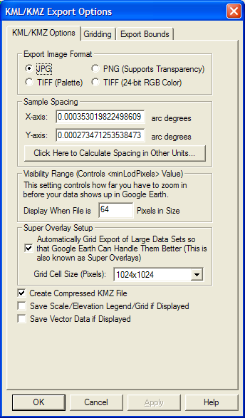
Export KML/KMZ CommandThe Export KML/KMZ command allows the user to export any loaded raster, vector, and elevation grid data sets to a KML/KMZ format file for display in Google Earth. If you are wanting to export a vector KML/KMZ file from loaded vector data, use the File->Export Vector Data->Export KML/KMZ menu command instead.
When selected, the command displays the KML/KMZ Export Options dialog (pictured below) which allows the user to setup the export. The dialog consists of a KML/KMZ Options panel, a Gridding panel, and an Export Bounds panel which allows the user to set up the portion of the loaded data they wish to export.
The KML/KMZ Options panel allows the user to set up the target image format for storage and the sample spacing, as well as other options such as whether to store all of the resulting files in a KMZ file (recommended) and whether or not to render and save loaded vector data. There is also an option to automatically grid the data on export (this creates what is known as a SuperOverlay). Enabling this option allows very large quantities of data to be efficiently viewed using Google Earth. When using this option you can also control the tile size to use when creating the super overlays. For very large exports the larger sizes (1024x1024 or 2048x2048) are recommended.
Note: Only registered users of Global Mapper are able to export data to any format.
Export Leveller Heightfield CommandThe Export Leveller Heightfield command allows the user to export any loaded elevation grid data sets to a Leveller Heightfield file for use with the Daylon Leveller application.
When selected, the command displays the Leveller Heightfield Export Options dialog which allows the user to setup the export. The dialog consists of a General options panel which allows the user to set up the grid spacing and vertical units, a Gridding panel, and an Export Bounds panel which allows the user to set up the portion of the loaded data they wish to export.
Note: Only registered users of Global Mapper are able to export data to any format.
Export Lidar LAS CommandThe Export Lidar LAS command allows the user to export any loaded elevation grid data sets to Lidar LAS format files.
When selected, the command displays the Lidar LAS Export Options dialog which allows the user to setup the export. The dialog consists of a General options panel which allows the user to set up the grid spacing and vertical units, a Gridding panel, and an Export Bounds panel which allows the user to set up the portion of the loaded data they wish to export.
Note: Only registered users of Global Mapper are able to export data to any format.
Export NITF CommandThe Export NITF command allows the user to export any loaded raster, vector, and elevation grid data sets to a NITF (National Imagery Transmission Format) file.
When selected, the command displays the NITF Export Options dialog which allows the user to setup the export. The dialog consists of a General options panel which allows the user to set up the pixel spacing, a Gridding panel, and an Export Bounds panel which allows the user to set up the portion of the loaded data they wish to export.
Note: Only registered users of Global Mapper are able to export data to any format.
Export Optimi Terrain File CommandThe Export Optimi Terrain File command allows the user to export any loaded elevation grid data sets to an Optimi Terrain format grid file. These terrain files can be used with applications from Optimi.
When selected, the command displays the Optimi Terrain Export Options dialog which allows the user to setup the export. The dialog consists of a General options panel which allows the user to set up the grid spacing and vertical units, a Gridding panel, and an Export Bounds panel which allows the user to set up the portion of the loaded data they wish to export.
Note: Only registered users of Global Mapper are able to export data to any format.
Export PGM File CommandThe Export PGM File command allows the user to export any loaded elevation grid data sets to a PGM grayscale grid file. These grid files can be used with any software application that supports PGM files.
When selected, the command displays the PGM Export Options dialog which allows the user to setup the export. The dialog consists of a General options panel which allows the user to set up the grid spacing and vertical units, a Gridding panel, and an Export Bounds panel which allows the user to set up the portion of the loaded data they wish to export.
Note: Only registered users of Global Mapper are able to export data to any format.
Export PLS-CADD XYZ File CommandThe Export PLS-CADD XYZ File command allows the user to export any loaded elevation grid data sets to a PLS-CADD XYZ format grid file. These grid files can be used with the PLS-CADD software application.
When selected, the command displays the PLS-CADD XYZ Export Options dialog which allows the user to setup the export. The dialog consists of a General options panel which allows the user to set up the grid spacing and vertical units, a Gridding panel, and an Export Bounds panel which allows the user to set up the portion of the loaded data they wish to export.
Note: Only registered users of Global Mapper are able to export data to any format.
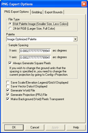
Export PNG CommandThe Export PNG command allows the user to export any loaded data sets to a PNG file.
When selected, the command displays the PNG Export Options dialog which allows the user to setup the export. The dialog consists of an Options panel (pictured below), which allows the user to select whether to export an 8-bit palette-based PNG or a 24-bit RGB PNG file, as well as other applicable options, a Gridding panel, and an Export Bounds panel which allows the user to set up the portion of the loaded data they wish to export.
Note: Only registered users of Global Mapper are able to export data to any format.
Export RockWorks Grid CommandThe Export RockWorks Grid command allows the user to export any loaded elevation grid data sets to a RockWorks Grid format file.
When selected, the command displays the RockWorks Grid Export Options dialog which allows the user to setup the export. The dialog consists of a General options panel which allows the user to set up the grid spacing and vertical units, a Gridding panel, and an Export Bounds panel which allows the user to set up the portion of the loaded data they wish to export.
Note: Only registered users of Global Mapper are able to export data to any format.
Export STL CommandThe Export STL command allows the user to export any loaded elevation grid data sets to a STL format file for use with some CAD systems.
When selected, the command displays the STL Export Options dialog which allows the user to setup the export. The dialog consists of a General options panel which allows the user to set up the grid spacing and vertical units, a Gridding panel, and an Export Bounds panel which allows the user to set up the portion of the loaded data they wish to export.
Note: Only registered users of Global Mapper are able to export data to any format.
Export Surfer Grid (ASCII Format) CommandThe Export Surfer Grid (ASCII Format) command allows the user to export any loaded elevation grid data sets to an ASCII format Surfer Grid file.
When selected, the command displays the Surfer Grid Export Options dialog which allows the user to setup the export. The dialog consists of a General options panel which allows the user to set up the grid spacing and vertical units, a Gridding panel, and an Export Bounds panel which allows the user to set up the portion of the loaded data they wish to export.
Note: Only registered users of Global Mapper are able to export data to any format.
Export Surfer Grid (Binary v6 Format) CommandThe Export Surfer Grid (Binary v6 Format) command allows the user to export any loaded elevation grid data sets to a binary format Surfer Grid file compatible with Surfer v6 and above. Binary format Surfer Grids will be smaller than their ASCII-format cousins, so if you can use the binary format I would suggest it.
When selected, the command displays the Surfer Grid Export Options dialog which allows the user to setup the export. The dialog consists of a General options panel which allows the user to set up the grid spacing and vertical units, a Gridding panel, and an Export Bounds panel which allows the user to set up the portion of the loaded data they wish to export.
Note: Only registered users of Global Mapper are able to export data to any format.
Export Surfer Grid (Binary v7 Format) CommandThe Export Surfer Grid (Binary v7 Format) command allows the user to export any loaded elevation grid data sets to a binary format Surfer Grid file compatible with Surfer v7 and above. Binary format Surfer Grids will be smaller than their ASCII-format cousins, so if you can use the binary format I would suggest it.
When selected, the command displays the Surfer Grid Export Options dialog which allows the user to setup the export. The dialog consists of a General options panel which allows the user to set up the grid spacing and vertical units, a Gridding panel, and an Export Bounds panel which allows the user to set up the portion of the loaded data they wish to export.
Note: Only registered users of Global Mapper are able to export data to any format.
Export Terragen Terrain File CommandThe Export Terragen Terrain File command allows the user to export any loaded elevation grid data sets to a Terragen terrain file.
When selected, the command displays the Terragen Export Options dialog which allows the user to setup the export. The dialog consists of a General options panel which allows the user to set up the grid spacing and an Export Bounds panel which allows the user to set up the portion of the loaded data they wish to export.
Note: Only registered users of Global Mapper are able to export data to any format.
Export Vertical Mapper (MapInfo) Grid File CommandThe Export Vetical Mapper (MapInfo) Grid File command allows the user to export any loaded elevation grid data sets to a Vertical Mapper GRD format file.
When selected, the command displays the Vertical Mapper Export Options dialog which allows the user to setup the export. The dialog consists of a General options panel which allows the user to set up the grid spacing and vertical units, a Gridding panel, and an Export Bounds panel which allows the user to set up the portion of the loaded data they wish to export.
Note: Only registered users of Global Mapper are able to export data to any format.
Export Vulcan3D Triangulation File CommandThe Export Vulcan3D Triangulation File command allows the user to export any loaded elevation grid data sets to a Vulcan3D triangulation file.
When selected, the command displays the Vulcan3D Export Options dialog which allows the user to setup the export. The dialog consists of a General options panel which allows the user to set up the grid spacing and vertical units, a Gridding panel, and an Export Bounds panel which allows the user to set up the portion of the loaded data they wish to export.
Note: Only registered users of Global Mapper are able to export data to any format.
Export VRML CommandThe Export VRML command allows the user to export any loaded elevation grid data and raster data sets to a VRML file for display in a VRML viewer, such as the Cortona VRML Client.
When selected, the command displays the VRML World File Export Options dialog which allows the user to setup the export. The dialog consists of a General options panel which allows the user to set up the grid spacing, vertical exaggeration, and compression options, and an Export Bounds panel which allows the user to set up the portion of the loaded data they wish to export.
Note: Only registered users of Global Mapper are able to export data to any format.
Export Bing Maps (Virtual Earth) Tiles CommandThe Export Bing Maps (Virtual Earth) Tiles command allows the user to export any loaded data to JPG or PNG files tiled in the configuration required for display in using the Microsoft Bing Maps (Virtual Earth) interface. This command will create both the image tiles and a sample HTML file for displaying the data with the Bing Maps (Virtual Earth) interface. You can just load the HTML file into your web browser to view the data once the export is over. You can also customize the HTML file however you need to.
When you select the command, the Bing Maps Export Options dialog (pictured below) appears allowing you to setup the export. This dialog allows you to specify the display name of the map set in your web browser, the zoom level setup, the format of the imagery, and some additional options. There is also an Export Bounds panel which allows the user to set up the portion of the loaded data they wish to export.
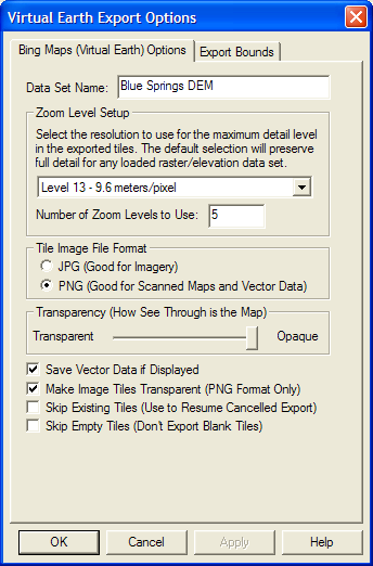
Note: Users without a permanent registration key that export Virtual Earth tiles will get a large diagonal DEMO symbol across the image. Registered users will not see that symbol on their output.
Export World Wind Tiles CommandThe Export World Wind Tiles command allows the user to export any loaded data to JPG or PNG files tiled in the configuration required by NASA's World Wind application. This command will create both the image tiles and the XML file required for World Wind to use the data. You should place the generated .xml file in the Config\Earth folder under your World Wind installation folder in order for it to be picked up by World Wind.
When you select the command, the World Wind Export Options dialog (pictured below) appears allowing you to setup the export. This dialog allows you to specify the display name of the map set in World Wind, the base directory to which the directory tree of map tiles will be exported, the zoom level setup, the format of the imagery, and some additional options. There is also an Export Bounds panel which allows the user to set up the portion of the loaded data they wish to export.
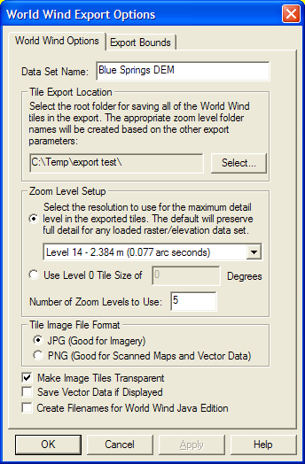
Note: Users without a permanent registration key that export World Wind tiles will get a large diagonal DEMO symbol across the image. Registered users will not see that symbol on their output.
Export Zoomify Tiles CommandThe Export Zoomify Tiles command allows the user to export any loaded data to JPG files tiled in the configuration required by the Zoomify viewer. This command will create both the image tiles and the XML file required for Zoomify to use the data. You will also need the Zoomify plugin to allow viewing the data. Global Mapper is not allowed to distribute that, so you will have to obtain it from Zoomify yourself.
When you select the command, the Zoomify Export Options dialog (pictured below) appears allowing you to setup the export. This dialog allows you to specify the sample spacing and some additional options. There is also an Export Bounds panel which allows the user to set up the portion of the loaded data they wish to export.

Note: Only registered users of Global Mapper are able to export data to any format.
Export XYZ Grid CommandThe Export XYZ Grid command allows the user to export any loaded elevation grid data sets to a comma-delimited ASCII XYZ file. Each grid point will be represented as follows (actual coordinate delimiter is configurable):
x-coordinate,y-coordinate,z-coordinate
When selected, the command displays the XYZ Grid Export Options dialog which allows the user to setup the export. The dialog consists of a General options panel which allows the user to set up the grid spacing and vertical units, a Gridding panel, and an Export Bounds panel which allows the user to set up the portion of the loaded data they wish to export.
Note: Only registered users of Global Mapper are able to export data to any format.
Export Zmap Plus Grid File CommandThe Export Zmap Plus Grid File command allows the user to export any loaded elevation grid data sets to a Zmap Plus Grid format file.
When selected, the command displays the Zmap Plus Grid Export Options dialog which allows the user to setup the export. The dialog consists of a General options panel which allows the user to set up the grid spacing and vertical units and an Export Bounds panel which allows the user to set up the portion of the loaded data they wish to export.
Note: Only registered users of Global Mapper are able to export data to any format.
The commands on the Export Vector Data submenu allow the user to export loaded vector data to various formats.
Export Arc Ungenerate CommandThe Export Arc Ungenerate commands allows the user to export any loaded vector data sets to an Arc Ungenerate format file.
When selected, the command displays the Arc Ungenerate Export Options dialog which consists of an Export Bounds panel that allows the user to set up the portion of the loaded vector data they wish to export.
Note: Only registered users of Global Mapper are able to export data to any format.
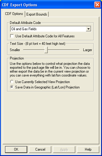
Export CDF CommandThe Export CDF command allows the user to export any loaded vector data sets to a CDF (Common Data Format) file.
When selected, the command displays the CDF Export Options dialog (pictured below) which allows the user to set up the export. The dialog consists of a CDF Options panel which allows the user to set up the attribute code to assign to features and the text size in the export file, and an Export Bounds panel which allows the user to set up the portion of the loaded vector data they wish to export.
If the Use Default Attribute for All Features option is checked, the attribute selected in the Default Attribute Code panel will be used for all features. Otherwise, the selected attribute will only be used for those features whose Global Mapper classification could not be automatically mapped to one of the CDF attributes.
Note: Only registered users of Global Mapper are able to export data to any format.
Export CSV CommandThe Export CSV command allows the user to export any loaded point data sets to a CSV (Comma Separated File) file.
When selected, the command displays the CSV Export Options dialog which allows the user to set up the export. The dialog consists of an Options panel which allows the user to set up whether or not to include an elevation attribute for each point as well as whether to include the name of each column in the file as the first row in the file. There is also an Export Bounds panel which allows the user to set up the portion of the loaded point data they wish to export.
ADVANCED USERS - In Global Mapper v11.02 and later you can customize the number of decimal digits written out for the X and Y coordinates for a CSV export through the use of a DWORD registry key 'HKEY_CURRENT_USER\Software\Global Mapper\ASCIIExportCoordPrecision'. For example, set this value to 6 to get 6 decimal digits for each X, Y, and Z coordinate.
Note: Only registered users of Global Mapper are able to export data to any format.
Export Delft3D (LDB) CommandThe Export Delft3D (LDB) command allows the user to export any loaded vector line data sets to a Delft3D (LDB) format file.
When selected, the command displays the Delft3D Export Options dialog which consists of an Export Bounds panel that allows the user to set up the portion of the loaded vector data they wish to export.
Note: Only registered users of Global Mapper are able to export data to any format.
Export DeLorme Text File CommandThe Export DeLorme Text File command allows the user to export any loaded vector features to one of 3 text formats that can be loaded into select DeLorme mapping products.
When selected, the command displays the DeLorme Text Polygon Export Options dialog which consists of an Export Bounds panel that allows the user to set up the portion of the loaded vector data they wish to export.
Note: Only registered users of Global Mapper are able to export data to any format.
Export DGN CommandThe Export DGN command allows the user to export any loaded vector data to a MicroStation DGN v8 format file.
When selected, the command displays the DGN Export Options dialog (pictured below) which allows the user to set up the export. The dialog consists of a DGN Options panel, a Gridding panel, and an Export Bounds panel which allows the user to set up the portion of the loaded vector data they wish to export.

The Text Size section allows the user to control how large display label text will be in the created file. The Unit Resolution value is used to specify the resolution unit saved in the DGN file. If the Generate PRJ File option is checked, a .prj projection file describing the projection of the coordinates in the file will automatically be created. If the Generate 3D DGN File if 3D Features Present option is checked, the entire DGN file will be marked as 3D and any features that have a elevation data associated with them will be stored as 3D features. If the Generate Tags for Feature Attributes option is checked, any attributes associated with exported features will be saved as tags in the resulting file. Note that this can significantly slow down your export in some cases. If the Set Global Origin to the Lower Left of Design Plane Rather than the Center of the Design Plane option is set, the global origin is set to the minimum valid negative values rather than at (0,0) as is standard. If the Replace Dark Line Colors with White option is set, any lines that are near black in color will be replaced with a white line automatically. This is useful for getting dark colored lines to show up when the exported DGN file is viewed in an application that uses a black background.
Note: Only registered users of Global Mapper are able to export data to any format.
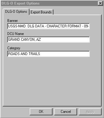
Export DLG-O CommandThe Export DLG-O command allows the user to export any loaded vector data sets to a native format USGS DLG-O (Digital Line Graph Optional format) file.
When selected, the command displays the DLG-O Export Options dialog (pictured below) which allows the user to set up the export. The dialog consists of a DLG-O Options panel which allows the user to set up the banner name, DCU (digital cartographic unit or quad name), and category name, a Gridding panel, and an Export Bounds panel which allows the user to set up the portion of the loaded vector data they wish to export. If possible, the fields on the DLG-O Options panel are automatically filled in with the best guesses available based on the currently loaded data. The user is free to change the values to fit their needs.
Note: Only registered users of Global Mapper are able to export data to any format.
Export DXF CommandThe Export DXF command allows the user to export any loaded vector data sets to an AutoCAD DXF format file.
When selected, the command displays the DXF Export Options dialog (pictured below) which allows the user to set up the export. The dialog consists of a DXF Options panel, a Gridding panel, and an Export Bounds panel which allows the user to set up the portion of the loaded vector data they wish to export.
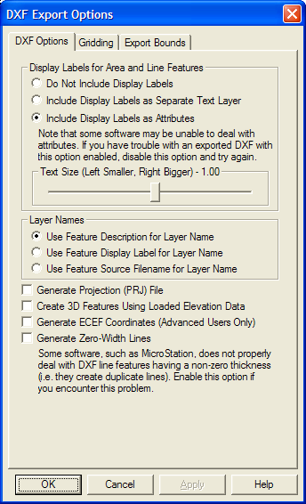
The Display Labels section allows you to control if you want feature display labels included in the DXF files and, if so, whether you want them represented as TEXT entities in their own layer (called FEATURE_LABEL) or as DXF attributes. The default is to have them included as attributes associated with each feature. As some software packages cannot handle attributes in DXF files, you may have to switch to a different option (with the associated loss of information) to get your exported DXF files to work with some software packages. If you would like line features to have rotated labels running along the line associated with them, you have to use the option to Include Display Labels as Separate Text Layer.
The Layer Names section allows you to control how the layer names used in the exported DXF file are generated. You can choose to use the feature description, feature display label, or feature source filename as the layer name in the exported file. If you choose to use the display label as the layer name, any features that do not have a display label will use the feature description as the layer name in the exported file.
If selected, the Generate Projection (PRJ) File option causes a projection file describing the ground reference system of the DXF file to be generated in addition to the DXF file itself. The PRJ file will have the same name as the DXF file with the .prj extension.
If selected, the Create 3D Features Using Loaded Elevation Data option will cause any underlying elevation data (like DEMs) to be used to retrieve elevation values for 2D features being exported and generate new 3D features in the exported DXF file. The units used by the elevation values are determined by the Elevation Display/Export Units setting on the Vertical Options tab of the Configuration dialog.
If selected, the Generate ECEF Coordinates option will cause the exported DXF file to use Earth-Centered Earth-Fixed (ECEF) XYZ coordinate values rather than XY values in the current export projection.
If selected, the Generate Zero-Width Lines option causes and line features created in the DXF file to be marked as having zero width. Use this option if you intend to use the resulting DXF file with a product such as MicroStation which has problems with lines of non-zero thickness.
Note that if you export features of the TIN Face Area area type they will be exported as 3D Face features in the generated DXF file rather than 3D polylines, allowing you to easily get a usable TIN surface for use in other applications, like 3DS Max.
Note: Only registered users of Global Mapper are able to export data to any format.
Export DWG CommandThe Export DWG command allows the user to export any loaded vector data sets to an AutoCAD Drawing (DWG) format file.
When selected, the command displays the DWG Export Options dialog (pictured below) which allows the user to set up the export. The dialog consists of a DWG Options panel, a Gridding panel, and an Export Bounds panel which allows the user to set up the portion of the loaded vector data they wish to export.
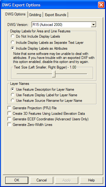
The DWG Version section allows you to select which DWG version to create.
The Display Labels section allows you to control if you want feature display labels included in the DWG files and, if so, whether you want them represented as TEXT entities in their own layer (called FEATURE_LABEL) or as DWG attributes. The default is to have them included as attributes associated with each feature. As some software packages cannot handle attributes in DWG files, you may have to switch to a different option (with the associated loss of information) to get your exported DWG files to work with some software packages. If you would like line features to have rotated labels running along the line associated with them, you have to use the option to Include Display Labels as Separate Text Layer.
The Layer Names section allows you to control how the layer names used in the exported DWG file are generated. You can choose to use the feature description, feature display label, or feature source filename as the layer name in the exported file. If you choose to use the display label as the layer name, any features that do not have a display label will use the feature description as the layer name in the exported file.
If selected, the Generate Projection (PRJ) File option causes a projection file describing the ground reference system of the DWG file to be generated in addition to the DWG file itself. The PRJ file will have the same name as the DWG file with the .prj extension.
If selected, the Create 3D Features Using Loaded Elevation Data option will cause any underlying elevation data (like DEMs) to be used to retrieve elevation values for 2D features being exported and generate new 3D features in the exported DWG file. The units used by the elevation values are determined by the Elevation Display/Export Units setting on the Vertical Options tab of the Configuration dialog.
If selected, the Generate ECEF Coordinates option will cause the exported DWG file to use Earth-Centered Earth-Fixed (ECEF) XYZ coordinate values rather than XY values in the current export projection.
If selected, the Generate Zero-Width Lines option causes and line features created in the DWG file to be marked as having zero width. Use this option if you intend to use the resulting DWG file with a product such as MicroStation which has problems with lines of non-zero thickness.
Note: Only registered users of Global Mapper are able to export data to any format.
Export Garmin TRK (PCX5) File CommandThe Export Garmin TRK (PCX5) File command allows the user to export any loaded vector line data to a Garmin TRK (PCX5) format file. This file can be imported by a wide variety of GPS software, such as Garmin's MapSource®, to facilitate transferring track logs to a GPS unit.
When selected, the command displays the Garmin TRK Format Export Options dialog which allows the user to set up the export. The dialog consists of an Export Bounds panel which allows the user to set up the portion of the loaded vector data they wish to export.
Note: Only registered users of Global Mapper are able to export data to any format.
Export Garmin WPT (PCX5) File CommandThe Export Garmin WPT (PCX5) File command allows the user to export any loaded named point data to a Garmin WPT (PCX5) format file. This file can be imported by a wide variety of GPS software, such as Garmin's MapSource®, to facilitate transferring waypoints to a GPS unit.
When selected, the command displays the Garmin WPT Format Export Options dialog which allows the user to set up the export. The dialog consists of an Export Bounds panel which allows the user to set up the portion of the loaded vector data they wish to export.
Note: Only registered users of Global Mapper are able to export data to any format.
Export GOG (Generalized Overlay Graphics) CommandThe Export GOG (Generalized Overlay Graphics) command allows the user to export any loaded vector data sets to a GOG format file.
When selected, the command displays the GOG Export Options dialog which allows the user to set up the export. The dialog consists of an Export Bounds panel which allows the user to set up the portion of the loaded vector data they wish to export.
Note: Only registered users of Global Mapper are able to export data to any format.
Export GPX (GPS eXchange Format) CommandThe Export GPX (GPS eXchange Format) commands allows the user to export any loaded point and line data to a GPX (GPS eXchange Format) file.
When selected, the command displays the GPX Export Options dialog which consists of an Export Bounds panel that allows the user to set up the portion of the loaded vector data they wish to export. If you want to fill in the <cmt> field of a feature during a GPX export, simply add a COMMENT attribute to the feature with the desired comment.
Note: Only registered users of Global Mapper are able to export data to any format.
Export InRoads ASCII CommandThe Export InRoads ASCII command allows the user to export any loaded vector data sets to an InRoads ASCII format file.
When selected, the command displays the InRoads ASCII Export Options dialog which allows the user to set up the export. The dialog consists of an Export Bounds panel which allows the user to set up the portion of the loaded vector data they wish to export.
Note: Only registered users of Global Mapper are able to export data to any format.
Export KML/KMZ CommandThe Export KML/KMZ command allows the user to export any loaded vector data sets to a KML/KMZ format file for use with Google Earth.
When selected, the command displays the KML/KMZ Export Options dialog (pictured below) which allows the user to set up the export. The dialog consists of a KML/KMZ Options panel, a Gridding panel, and an Export Bounds panel which allows the user to set up the portion of the loaded vector data they wish to export.
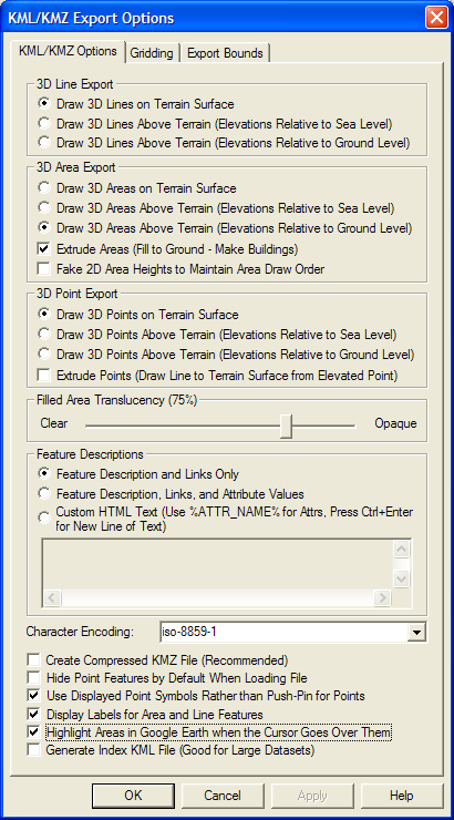
The 3D Line Export, 3D Area Export, and 3D Point Export sections allow the user to control whether or not area, line, and point features with elevation values associated with them are drawn at the terrain surface or at the elevation values associated with the feature. You can specify whether the elevation values are relative to ground level or sea level if drawing the features above the terrain. If area features are drawn above the terrain, the Extrude Areas option allows you to control whether or not they will also be extruded, which means they will extend back to the terrain surface, making them look like solid 3D features. If this option is not checked, the areas will just be drawn in space as a surface and not a 3D closed object. If the Fake 2D Area Heights to Maintain Area Draw Order option is checked, exported 2D area features will be assigned fake elevation values in order to attempt to get them to layer properly when displayed in Google Earth. This is only necessary if you have overlapping areas that do not display in the correct order without this option checked. If point features are drawn above the terrain, the Extrude Points option allows you to control whether or not a thin line is drawn from the terrain surface at the location of the point to the floating symbol above the terrain surface. Enabling this option makes it easier to locate exactly where a point lies relative to the surface.
The Filled Area Translucency section allows the user to control the degree to which filled polygons are see-through in the created file.
The Feature Descriptions section allows you to setup what is contained in the description for each feature in the generated file. You can choose to include only the feature description and links to any files associated with a feature, you can choose to add attributes to this, or you can choose to provide your own HTML text to use for the feature description. If you use the HTML text option, you can embed the values of attributes from the feature in the text by enclosing the attribute name in percent signs, like %ATTR_NAME%. In addition to the name of attributes, you can also specify <Feature Name>, <Feature Desc>, or <Feature Type> as the attribute name to get the feature display label, description, or type name embedded in the result. If you need to embed an actual percent sign in your result, simply use two percent signs consecutively as an escape sequence.
The following additional options are also available:
For advanced users, you can also customize what is displayed in the balloon text that appears in Google Earth when you click on a point. You are able to customize the <Balloon Style> tag to use text with the string value stored in the registry at 'HKEY_CURRENT_USER\Software\Global Mapper\KmlExport_BalloonStyle'. If that value is empty the default setting from Google Earth will be used.
Note: Only registered users of Global Mapper are able to export data to any format.
Export Landmark Graphics CommandThe Export Landmark Graphics command allows the user to export any loaded vector data sets to a Landmark Graphics format file.
When selected, the command displays the Landmark Graphics Export Options dialog which allows the user to set up the export. The dialog consists of an Export Bounds panel which allows the user to set up the portion of the loaded vector data they wish to export.
Note: Only registered users of Global Mapper are able to export data to any format.
Export Lidar LAS CommandThe Export Lidar LAS command allows the user to export any loaded 3D vector data sets (like 3D point clouds loaded from other LAS files) to new Lidar LAS format files. If the source data came from a Lidar format file, like a LAS or MrSid Lidar file, the attributes from the original data will be maintained. For other points, in addition to the base position and elevation, if there is an INTENSITY attribute available for the point, the value of that attribute will be exported as the intensity for the point in the exported LAS file.
When selected, the command displays the Lidar LAS Export Options dialog which allows the user to setup the export. The dialog consists of a Gridding panel, and an Export Bounds panel which allows the user to set up the portion of the loaded data they wish to export.
Note: Only registered users of Global Mapper are able to export data to any format.
Export Lowrance LCM CommandThe Export Lowrance LCM (MapCreate) command allows the user to export any loaded vector data sets to a Lowrance LCM format file for use in Lowrance brand GPS devices. This allows you to create custom maps for Lowrance devices from your data. Type assignment will be done based on the built-in type assignments. In addition, the MP_TYPE attribute classification used for Polish MP exports for Garmin devices will also work for Lowrance exports, so if you provide custom classifications via the MP_TYPE attribute the type mapping should work for Lowrance exports as well.
When selected, the command displays the Lowrance LCM Export Options dialog which allows the user to set up the export. The dialog consists of a Gridding panel and an Export Bounds panel which allows the user to set up the portion of the loaded vector data they wish to export.
Note: Only registered users of Global Mapper are able to export data to any format.
Export Lowrance USR CommandThe Export Lowrance USR command allows the user to export any loaded vector data sets to a Lowrance USR format file for use in Lowrance brand GPS devices.
When selected, the command displays the Lowrance USR Export Options dialog which allows the user to set up the export. The dialog consists of a Gridding panel and an Export Bounds panel which allows the user to set up the portion of the loaded vector data they wish to export.
Note: Only registered users of Global Mapper are able to export data to any format.
Export MapGen CommandThe Export MapGen command allows the user to export any loaded vector data sets to a MapGen format file.
When selected, the command displays the MapGen Export Options dialog which allows the user to set up the export. The dialog consists of an Export Bounds panel which allows the user to set up the portion of the loaded vector data they wish to export.
Note: Only registered users of Global Mapper are able to export data to any format.
Export MapInfo MIF/MID CommandThe Export MapInfo MIF/MID command allows the user to export any loaded vector data sets to a MapInfo MIF/MID format file.
When selected, the command displays the MapInfo Export Options dialog which allows the user to set up the export. The dialog consists of a Gridding panel and an Export Bounds panel which allows the user to set up the portion of the loaded vector data they wish to export.
Note: Only registered users of Global Mapper are able to export data to any format.
Export MapInfo TAB/MAP CommandThe Export MapInfo TAB/MAP command allows the user to export any loaded vector data sets to a MapInfo TAB/MAP format file.
When selected, the command displays the MapInfo Export Options dialog which allows the user to set up the export. The dialog consists of a Gridding panel and an Export Bounds panel which allows the user to set up the portion of the loaded vector data they wish to export.
Note: Only registered users of Global Mapper are able to export data to any format.
Export MatLab CommandThe Export MatLab command allows the user to export any loaded vector data sets to a MatLab format file.
When selected, the command displays the MatLab Export Options dialog which allows the user to set up the export. The dialog consists of an Export Bounds panel which allows the user to set up the portion of the loaded vector data they wish to export.
Note: Only registered users of Global Mapper are able to export data to any format.
Export Moss CommandThe Export Moss command allows the user to export any loaded area and line vector features to a Moss format file.
When selected, the command displays the Moss Export Options dialog which allows the user to set up the export. The dialog consists of an Export Bounds panel which allows the user to set up the portion of the loaded vector data they wish to export.
Note: Only registered users of Global Mapper are able to export data to any format.
Export NIMA ASC CommandThe Export NIMA ASC command allows the user to export any loaded vector data sets to a NIMA ASC format file that can be used on many shipboard radar displays.
When selected, the command displays the NIMA ASC Export Options dialog which allows the user to set up the export. The dialog consists of an Export Bounds panel which allows the user to set up the portion of the loaded vector data they wish to export.
Note: Only registered users of Global Mapper are able to export data to any format.
Export OSM (OpenStreetMap.org) XML CommandThe Export OSM (OpenStreetMap.org) XML command allows the user to export any loaded vector data sets to an OSM XML format file that can be used to provide new data to the OpenStreetMap.org web site.
When selected, the command displays the OSM XML Export Options dialog which allows the user to set up the export. The dialog consists of an Export Bounds panel which allows the user to set up the portion of the loaded vector data they wish to export.
Note: Only registered users of Global Mapper are able to export data to any format.
Export Platte River/WhiteStar/Geographix File CommandThe Export Platte River/Whitestar/Geographix File command allows the user to export any loaded area features to a Platte River Digitizer/Whitestar/Geographix Township/Range ASCII format file. These files can be used with several applications.
When selected, the command displays the Platte River Export Options dialog which allows the user to setup the export. The dialog consists of an Export Bounds panel which allows the user to set up the portion of the loaded data they wish to export.
The township, range, section, and meridian values saved for each area feature exported are derived either from the attribute values for the area feature or the display label for "Survey Section" area types. The following attribute values names are recognized for each field:
Note: Only registered users of Global Mapper are able to export data to any format.
Export PLS-CADD XYZ File CommandThe Export PLS-CADD XYZ File command allows the user to export any loaded vector data sets to a PLS-CADD XYZ format file. These files can be used with the PLS-CADD software application.
When selected, the command displays the PLS-CADD XYZ Export Options dialog which allows the user to setup the export. The dialog consists of an Export Bounds panel which allows the user to set up the portion of the loaded data they wish to export.
Note: Only registered users of Global Mapper are able to export data to any format.
Export Polish MP (cGPSMapper) CommandGetting Started with Global Mapper and cGPSMapper - Fantastic Guide to Creating Garmin-format Maps using Global Mapper, cGPSMapper, and the other supporting applications required to get your data into a Garmin unit as a new map.
The Export Polish MP command allows the user to export any loaded vector data sets to Polish MP format files. The Polish MP format is the input format used by the cGPSMapper application which creates custom maps for Garmin GPS units.
When selected, the command displays the Polish MP Export Options dialog (pictured below) which allows the user to set up the export. The dialog consists of a Map Options panel, a Gridding panel, and an Export Bounds panel which allows the user to set up the portion of the loaded vector data they wish to export.
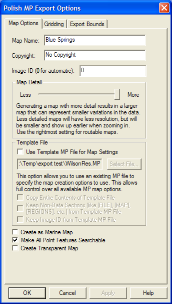
The Map Name and Copyright fields allow to specify the name to use for the final map when created as well as the copyright text to associate with the map.
The Map Detail section allows you to control at what zoom levels the final map will be viewable at. More detail results in a map that better represents the shape of the source data but that requires zooming further in to see the map, while less detail will result in a rougher map that shows up sooner. You should tailer this to the approximate scale of your source data, will the lowest detail setting approximating source vector data of around 1:250K scale and the highest detail setting representing 1:24K or better scale data.
Most built-in types already have a default zoom scale at which they will show up in built MP maps (this will translate to a Levels= value for the feature in the exported MP file based on the levels in the MP file header). For custom types and for types that you want to change the default zoom scale for, you can add a MP_BIT_LEVEL attribute to the feature itself or to the default attribute list for a feature type. The value of this attribute should specify the minimum MP zoom bit level that a feature should appear at. For example, if you use the maximum Map Detail setting with no template file, you will get a map with populated zoom levels at 24, 22, and 20 bits. If you wanted a feature to show up in just the lower 2 zoom levels of that map (the 24 and 22 bit resolution layers), you could add a MP_BIT_LEVEL attribute with a value of 22 to your feature or the default attribute list for that type, then that feature would get a Levels=2 value written to the exported MP file. If your map had less detail (say zoom levels of 21, 19, and 17 bits), the same feature would only show up in the most detailed 21 bit layer as features are always present in at least one layer of the map. If you want a feature to always show up at all zoom levels in your map regardless of what zoom levels are present, just add a MP_BIT_LEVEL attribute with a value of 1.
The Template File sections allows you to select a file to use as a template for the new MP file. The new file with use all of the settings from the selected template file except for the map ID (unless you check the Keep Image ID from Template MP File option) and, if you provide a map name, the map name. This includes the Dictionary setting and all levels settings. This provides a way for advanced users to set up one MP file exactly how they want and then export new maps with the same settings. You can also check the Copy Entire Contents of Template File option to have everything from the template file copied to the new file verbatim, including any feature data in the template file.
If selected, the Create as Marine Map option specifies that the created MP file will be marked as a marine map and marine features will be used if appropriate. Note that the Marine version of cGPSMapper is required to create marine maps.
The Make All Point Features Searchable controls whether or not all point features in the final map created from the MP file should be searchable on the GPS device. If the Create Transparent Map option is selected the map will be marked as transparent and any data under the map will show through.
When Global Mapper exports loaded vector data to a MP file, it will automatically attempt to determine the best type to save in the MP file based on the classification of the feature in Global Mapper. If no type mapping is known, the name of the assigned Global Mapper classification will be used for the 'Type' value in the MP file. If you updated your RgnTypes.txt file in your cGPSMapper folder with the type names and the appropriate type number, you can make this work as well. You can also manually specify the type number to use for a feature by adding an attribute named MP_TYPE with the type value to use as the attribute value. If the value that you provide is for a marine type you should also provide an attribute with a name of MARINE and a value of Y. You can also override the default type mapping for built-in types by adding a default attribute list for the type on the * Styles tab of the Configuration dialog. Just add a MP_TYPE attribute to the default attribute list for a type to manually specify what type to use in exported MP files for a given Global Mapper type.
Global Mapper will automatically convert exported data to the appropriate projection and datum for export so that the Polish MP file will be correctly positioned. By default this will be lat/lon degrees with the WGS84 datum, although if you use a template file that specified a different recognized datum, Global Mapper will instead convert to that datum automatically. In any case, Global Mapper will always automatically do the right thing.
Advanced Users: If you aren't use a template to configure your export, you can customize the values used for several settings in the header for adding registry keys. The following values are supported:
Note: Only registered users of Global Mapper are able to export data to any format.
Export SEGP1 CommandThe Export SEGP1 command allows the user to export any loaded 3D line and point vector data sets to a SEGP1 format file.
When selected, the command displays the SEGP1 Export Options dialog which allows the user to set up the export. The dialog consists of a Gridding panel and an Export Bounds panel which allows the user to set up the portion of the loaded vector data they wish to export.
Note: Only registered users of Global Mapper are able to export data to any format.
Export Shapefile CommandThe Export Shapefile command allows the user to export any loaded vector data sets to ESRI Shapefile format files.
When selected, the command displays the Shapefile Export Options dialog (pictured below) which allows the user to set up the export. The dialog consists of a File Selection panel, a Gridding panel, and an Export Bounds panel which allows the user to set up the portion of the loaded vector data they wish to export.
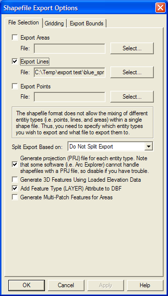
The Export Areas, Export Lines, and Export Points options enable area, line, and point export respectively. Pressing the Select... button next to each of those options allows you to select the name of the SHP file to generate. In addition to the SHP file containing the actual geometry of the features, an shape index file (SHX) and attribute database file (DBF) will be created as well with the same name as the SHP file.
In general, Global Mapper will automatically determine an appropriate field type and length for any attributes exported to the DBF file created along with a Shapefile based on the values of the attribute data being exported. However, if your input data includes Shapefiles or DBF files, the original field type and length for an attribute will be used unless the attribute values being exported make that impossible.
The Split Export Based On option allows you to split up your export into separate files based on the feature type/classification or the feature description. If you choose the Split on Feature Type option, you will get the export split based on the feature classification, except in the case of the unknown types, in which case the feature description will be used automatically. The type/description of the features stored in each file will be appended on to the end of the selected filenames.
If selected, the Generate Projection (PRJ) File option causes a projection file describing the ground reference system of the shapefile to be generated for each shapefile created. The PRJ files will have the same name as the SHP file with the .prj extension.
If selected, the Generate 3D Features Using Loaded Elevation Data option specifies that 3D objects should be created in the shapefile. The elevation stored for each vertex/point will be the first of the following which is available:
If selected, the Add Feature Type (LAYER) Attribute to DBF option specifies that the type description for each exported feature will be added as a LAYER attribute to the DBF file generated with the SHP file.
If selected, the Generate Multi-Patch Features for Areas option specifies that multi-patch features should be generated for area exports rather than normal polygon records. This is useful for exporting 3D models, such as those you would load from Google SketchUp SKP files.
WARNING: The Shapefile format uses a DBF file for attribute storage, which means that any attribute names are limited to 10 characters. Any attribute names longer than that will be truncated with a number potentially added on to maintain uniqueness among multiple long attribute names.
Note: Only registered users of Global Mapper are able to export data to any format.
Export Simple ASCII Text File CommandThe Export Simple ASCII Text File command allows the user to export any loaded vector data sets (i.e. areas, lines, and points) to a delimited ASCII text file. Each vertex in an area or line and the position of each point will be represented.
When selected, the command displays the ASCII Export Options dialog which allows the user to setup the export. The dialog consists of an Options panel (pictured below) and an Export Bounds panel which allows the user to set up the portion of the loaded data they wish to export.
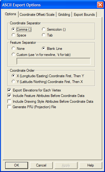
The Options panel allows the user to specify what character to user to separate the x, y, and z coordinates of each vertex. In addition, the user can specify that they wish to separate each vector feature with a blank line or some other custom separator text. The Coordinate Order section allows the user to control the order in which the X (easting/longitude) and Y (northing/latitude) coordinates are exported. The export of elevation data is controlled with the Export Elevations option. The Include Feature Attributes Before Coordinate Data and Include Drawing Style Attributes Before Coordinate Data options respectively control whether or not feature attributes or feature drawing style information is saved to the file on the lines preceding the coordinate data for a feature.
If elevations are being exported, Global Mapper first looks for an elevation associated with the vertex being exported. If no elevation is associated with the vertex, Global Mapper then checks all loaded elevation grid data in reverse order of display to see if any of them have an elevation at the vertex location. If so, that elevation is used.
ADVANCED USERS - In Global Mapper v11.02 and later you can customize the number of decimal digits written out for the X and Y coordinates for a Simple ASCII Text export through the use of a DWORD registry key 'HKEY_CURRENT_USER\Software\Global Mapper\ASCIIExportCoordPrecision'. For example, set this value to 6 to get 6 decimal digits for each X, Y, and Z coordinate.
Note: Only registered users of Global Mapper are able to export data to any format.
Export Surfer BLN CommandThe Export Surfer BLN command allows the user to export any loaded vector data sets to a Surfer BLN format file used by Golden Software's Surfer package to specify breaklines.
When selected, the command displays the Surfer BLN Export Options dialog which allows the user to set up the export. The dialog consists of an Export Bounds panel which allows the user to set up the portion of the loaded vector data they wish to export.
Note: Only registered users of Global Mapper are able to export data to any format.
Export SVG CommandThe Export SVG command allows the user to export any loaded vector data sets to a SVG (Scalable Vector Graphic) format file suitable for display on the web.
When selected, the command displays the SVG Export Options dialog which allows the user to set up the export. The dialog consists of an Export Bounds panel which allows the user to set up the portion of the loaded vector data they wish to export.
Note: Only registered users of Global Mapper are able to export data to any format.
Export Tom Tom OV2 CommandThe Export Tom Tom OV2 command allows the user to export any loaded point data sets to a Tom Tom OV2 format file for use in creating POI databases for Tom Tom GPS devices.
When selected, the command displays the Tom Tom OV2 Export Options dialog which allows the user to set up the export. The dialog consists of an Export Bounds panel which allows the user to set up the portion of the loaded vector data they wish to export.
Note: Only registered users of Global Mapper are able to export data to any format.
Export Tsunami OVR CommandThe Export Tsunami OVR command allows the user to export any loaded vector data sets to a Tsunami OVR format file for use in the Tsunami software package.
When selected, the command displays the Tsunami OVR Export Options dialog which allows the user to set up the export. The dialog consists of an Export Bounds panel which allows the user to set up the portion of the loaded vector data they wish to export.
Note: Only registered users of Global Mapper are able to export data to any format.
Export UKOOA P/190 CommandThe Export UKOOA P/190 command allows the user to export any loaded 3D line and point vector data sets to an UKOOA P/190 format file.
When selected, the command displays the UKOOA Export Options dialog which allows the user to set up the export. The dialog consists of a Gridding panel and an Export Bounds panel which allows the user to set up the portion of the loaded vector data they wish to export.
Note: Only registered users of Global Mapper are able to export data to any format.
Export WAsP MAP File CommandThe Export WAsP MAP File command allows the user to export loaded line and area features to a WAsP MAP format file for use with the WAsP (Wind Analysis and Application Program) application (http://www.wasp.dk/.
Only those line features with an elevation and/or valid roughness attributes will be exported. Only those area features with valid roughness attributes will be exported. Valid roughness attributes consist of a ROUGH_L and a ROUGH_R attribute containing numeric values for the left and right roughness for the feature. If neither of those attributes exist but a RV attribute is available, that value will be used for both the left and right roughness for that feature.
When selected, the command displays the WAsP MAP Export Options dialog which allows the user to setup the export. The dialog consists of an Export Bounds panel which allows the user to set up the portion of the loaded data they wish to export.
Note: Only registered users of Global Mapper are able to export data to any format.
Export ZMap+ XYSegId File CommandThe Export ZMap+ XYSegId File command allows the user to export loaded line and area features to a ZMap+ text format file for use with applications like Landmark Graphics..
When selected, the command displays the ZMap+ XYSegId Export Options dialog which allows the user to setup the export. The dialog consists of an Export Bounds panel which allows the user to set up the portion of the loaded data they wish to export.
This format costs of one line per each input coordinate, with the X coordinate followed by the Y coordinate (optionally with a Z if available), followed by the feature index in the file. The following is short sample of an output file with a couple of features:
    924800.1       10593255.0     1.
    919970.1       10590840.0     1.
    915623.0       10586976.0     1.
    914174.0       10579248.0     1.
    919487.0       10573451.0     1.
    927215.1       10569587.0     1.
    933977.3       10568138.0     1.
    938324.3       10575867.0     1.
    937358.3       10586493.0     1.
    934460.2       10593255.0     1.
    927698.3       10594221.0     1.
    924800.1       10593255.0     1.
    884645.6       10557271.0     2.
    887543.7       10549543.0     2.
    893822.8       10540849.0     2.
    900584.8       10539400.0     2.
    906380.8       10543264.0     2.
    907829.9       10554373.0     2.
    900584.8       10565965.0     2.
    895271.8       10567414.0     2.
    886094.7       10565965.0     2.
    884645.6       10557271.0     2.
    876917.6       10524427.0     3.
    870155.4       10518630.0     3.
    865808.5       10512834.0     3.
    861944.4       10503657.0     3.
    865325.6       10494963.0     3.
    871121.6       10493997.0     3.
    880781.6       10496895.0     3.
    889475.8       10499793.0     3.
    890924.8       10509936.0     3.
    889475.8       10518147.0     3.
    884645.6       10524910.0     3.
    876917.6       10524427.0     3.
Note: Only registered users of Global Mapper are able to export data to any format.
Batch Convert/ReprojectThe Batch Convert/Reproject command allows the user to easily convert multiple files in one format to another format.
When the command is selected, the user is first prompted to select the file type to convert from using the dialog pictured below. Once an input file type is selected, another dialog with a list of all compatible export file types is displayed, allowing the user to select what type of file to convert the input files to. Finally, after the input and output file types are selected, the Batch Convert dialog (pictured below) is displayed, allowing the user to set up the batch conversion.
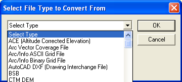
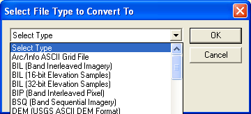
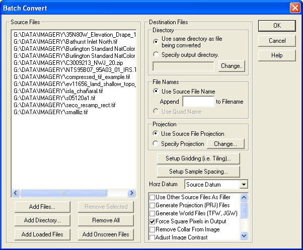
The Source Files section displays the list of source files currently selected to be converted. Pressing the Add Files... button allows the user to select additional files for conversion. Pressing the Add Directory... allows the user to easily add an entire directory's worth of source files to the to-be-converted list. All directories under the added one can be recursively searched if so desired by answering Yes to the dialog that pops up immediately after selecting the directory. Pressing the Add Loaded Files button causes all files loaded into the main Global Mapper view that match that batch convert input type to be added to the list of files to be converted. Pressing the Add Onscreen Files button causes all files loaded into the main Global Mapper view that are currently at least partially onscreen and that match the batch convert input type to be added to the list of files to be converted.
The Directory section allows the user to choose where they would like the newly created output files to be created. The Use same directory as file being converted option causes the output file created off of each source file to be created in the same directory as the source file. The Specify output directory option allows the user to choose a specific directory to output all of the newly created output files to.
The File Names section allows the user to choose whether the newly created output files should have the same file name as the source file they were created from (Use Source File Name option) or whether the more readable quadrangle name (if available) should be used as the file name for the newly created output file (Use Quad Name option). If the Use Source File Name option is selected, you can also specify an additional text string to append to each new filename to identify it.
The Projection section allows the user to choose whether or not each newly created output file should either use the same projection as the file that it was created from (Use Source File Projection option) or if each file should use a projection specified by pressing the Projection button. If the user selects to specify an output projection and they select a zoned projection like UTM or Gauss Krueger, they will have the option on the projection selection dialog to have the best zone for the center of the output map automatically used if they select the Automatically Select Best Zone option in the Zone box on the projection selection dialog.
The Setup Gridding (i.e. Tiling) button displays a dialog allowing the user to specify if and how to break up each file being converted into multiple new files. This option is only available when converting to a raster or gridded elevation format.
The Setup Sample Spacing button displays a dialog allowing the user to choose to either keep the sample spacing of source raster and elevation files when converting the selected or to specify a new sample spacing to resample all of the selected input files at when performing the conversion. This option is only available when converting to a raster or gridded elevation format.
The Horz Datum selection allows the user to choose the horizontal datum that each newly created output file should use. By default, each output file will use the same horizontal datum as the source file that it was created off of. Alternately, the user can specify to have all output files created in NAD27, NAD83, WGS72, or WGS84 with the appropriate offset being applied automatically.
The Vertical Units selection is present only for some conversions and controls the output elevation units.
The Palette selection is present only for some conversions and controls the palette, if any, used in the output files. The palette values are defined as follows:
The additional list of options varies depending on the particular conversion being performed. The meaning of those options is defined below:
You can also right click on the list of files to convert and choose to save that list of files to a text file. This can be a convenient way to start a Global Mapper script to do other processing on the files. Other right-click options include the ability to remove all archive files, like .zip and .tar.gz from the list and to fill the source files list with files listed in a text file.
Note: Only registered users of Global Mapper are able to perform batch conversions.
Combine Terrain Layers CommandThe Combine Terrain Layers command allows the user to generate a new gridded elevation (or other gridded value) layer by combining and/or comparing the elevation values from two other loaded terrain layers.
When selected, the command displays the Combine Terrain Options dialog which allows the user to set up generation of the new terrain layer. Once completed the new terrain layer is added to the Overlay Control Center and displayed.

The Combine Terrain Layers Options panel (displayed above) allows the user to select the name to assign to the newly generated layer, select the layers to combine to make the new layer, select the operation to perform when combining the new layer, and select the vertical units and sample spacing of the new layer. The available operations are described below:
Note: Only registered users of Global Mapper are able to combine terrain layers.
Generate Contours CommandThe Generate Contours command allows the user to generate equally spaced contour lines from any loaded elevation grid data.
When selected, the command displays the Contour Generation Options dialog (pictured below) which allows the user to set up the contour generation process.
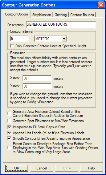
The Contour Options panel (displayed above) allows the user to set the contour interval and units as well as the grid spacing to use when generating the contours. In addition, options are available to generate isoheight area features in addition to contour lines as well as spot elevations at the highest and lowest points in the area over which the contours are generated. The smoothing option controls whether or not extra vertices are added along generated line and area features to improve their appearance. If you need to generate a huge amount of contour lines over a large area, the option to export the contours directly to a package file can be used in addition to the Gridding tab options to export those contours directly to package files to get around memory limitations. Note that the contour lines will be generated so that the higher elevations are to the left of the contour line.
The Simplification panel (displayed below) allows the user to set up the threshold at which points that don't contribute much to the shape of the generated contour are removed in order to generate lines with less vertices. The Gridding panel allows you to break up your contour generation into smaller pieces which can sometimes help reduce memory requirements when generating a very large amount of contour lines. The Export Bounds panel allows the user to set up the portion of the loaded elevation grid data they wish to consider when generating the contours.
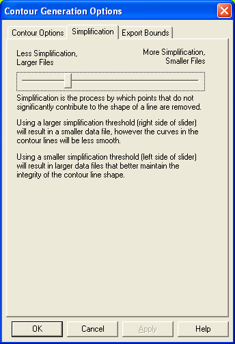
The Print command allows the user to print the contents of the current view window. When selected the Print dialog (picture below) is displayed, which allows the user to set up the print process.
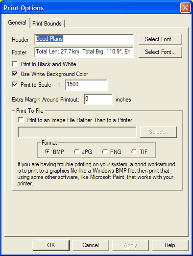
The Header field allows the user to specify text to be displayed above the printed map image. This text will be printed centered above the map image on the printout.
The Footer field allows the user to specify text to be displayed below the printed map image. This text will be printed centered below the map image on the printout. The footer text will default to the text displayed on the status bar for the active tool, such as the measurement information for the current measurement in the Measure Tool.
Selecting the Print in Black and White option causes the printout to be generated in black and white, rather than full color even when printing to a color printer. The generated image will be a 256-level grayscale image.
Selecting the Use White Background Color option causes any background areas being printed to be filled with white so as not to use any printer ink. Uncheck this option is you want the currently configured background color to be maintained on the printout.
The Extra Margin Around Printout setting allows you to specify an extra margin to draw around the output. This is useful when printing to things like a PDF file that do not have any natural margins like a printer does.
The Print To Scale option allows you to specify that you want the printed result to match a certain scale, like 1:1000. This means that one inch on the printed paper will correspond to 1000 inches in the real world. If you choose to print to a certain scale, the printout will be centered on the center of your current screen view, but the appropriate amount of information will be rendered to achieve the requested scale.
The Print To File section allows you to specify that the printout be directed to an image file rather than to the printer. This can be handy if you either want to save the results of the printout to email to someone or post on a web site, or you are having trouble printing and would like to print out the data generated by Global Mapper using another application.
The Print Bounds panel allows the user to select exactly what area to print (the default is the current screen contents). This panel behaves just like the Export Bounds panel found on most export dialogs.
Print Preview CommandThe Print Preview command allows the user to preview what a printout of the contents of the current view window would look like.
Print Setup CommandThe Print Setup command allows the user to setup their printer for printing the current view window.
Exit CommandThe Exit command closes the Global Mapper application.
View MenuThe View menu offers the following commands:
Use this command to display and hide the Toolbars, which includes buttons for some of the most common commands in Global Mapper. A check mark appears next to the menu item when the Toolbar is displayed
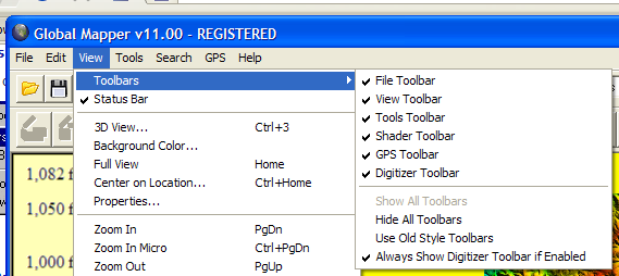

The status bar is displayed at the bottom of the Global Mapper window. To display or hide the status bar, use the Status Bar command in the View menu.
The left area of the status bar describes actions of menu items and toolbar icons. The left area of the status bar will also show color or elevation of the current pixel if it's over a raster image, or the description of the closest vector overlay component. If the nearest line feature to the cursor contains recognized addressing information, the address nearest the cursor will be displayed.
The right areas of the status bar indicate the current view scale and the current mouse position in both the global ground reference system and in the Position Display Format currently selected from the Configuration dialog.
BackgroundThe Background command brings up a color dialog box from which the user can select a color to be the new background color of your Global Mapper window. The background color selected will also be used to fill in areas of no data in exported raster imagery (i.e. GeoTIFF and JPG files).
Center on LocationThe Center on Location command allows the user to manually enter a location to recenter the view on, providing a quick and easy way to center yourself on a particular location.
Properties PropertiesThe Properties command displays a dialog listing properties about the current view window.
Full ViewThe Full View command zooms such that all of the currently loaded overlays fit in the view window. This command also places the overlays in the center of the view window.
Zoom InThe Zoom In command zooms the current view in by a factor of 2.
Zoom In MicroThe Zoom In Micro command zooms the current view in by a small amount.
Zoom OutThe Zoom Out command zooms the current view out by a factor of 2.
Zoom Out MicroThe Zoom Out Micro command zooms the current view out by a small amount.
Zoom To ScaleThe Zoom To Scale command zoom the current view to a user-specified scale. For example, to make one inch on the screen be equivalent to 1 mile of ground truth, you would enter a scale of 63360 (this is the number of inches in a mile).
Zoom To Spacing (Pixel Size)The Zoom To Spacing command zoom the current view so that each pixel on the screen represents a user-specified number of ground units.
Save Current ViewThe Save Current View command saves the current map view bounds. The saved view can later be restored by using the Restore Last Saved View command. This feature allows you to save a view at one spot, then pan and zoom around and load additional data, then restore your view to the saved spot in one simple operation.
Restore Last Saved ViewThe Restore Last Saved View command restore the map view to the location last saved using the Save Current View command.
Restore Last Drawn ViewThe Restore Last Drawn View command restore the map view to the view that was last drawn on the main map. You can use this to back up threw recently drawn view locations and zoom levels.
Name and Save Current ViewThe Name and Save Current View command associates the current map view bounds with a user-specified name. The saved view can later be restored from a list of named views using the Restore Named View command. This feature allows you to save multiple views with descriptive names, then easily restore those views at a later time.
Restore Named ViewThe Restore Named View command allows you to restore a previously saved map view. You can save map views for later restoration using the Name and Save Current View command.
Search MenuThe Search menu currently provides the following commands:
The Search By Name command allows for searching for features in all loaded vector data by name. When selected, the Find By Name dialog is displayed.
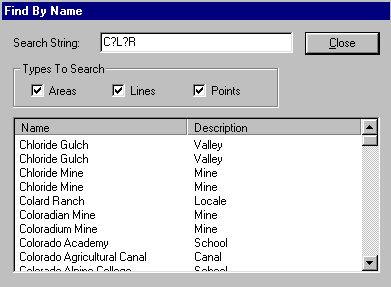
The Find By Name dialog displays a list of all of the vector features (areas,lines, and/or points) whose label starts with the search string specified in the Search String field. This field can contain the ? and * wildcard characters. In addition, one can control which vector object types (area,line, and/or point) to include in the search. Double-clicking on an item in the list will recenter the view on that object and show a bullseye on it (hold down the ALT key when double-clicking to not show the bullseye).
The Edit Selected button displays a dialog allowing the user to modify the name, feature type, and drawing style of any features selected.
The Delete Selected button will mark all selected features as deleted.
This dialog is particulary handy with the GNIS (Geographic Names) database which is freely available for download.
Search By Attributes, Name, and DescriptionThe Search By Attributes, Name, and Description command allows for searching for features in all loaded vector data by attribute value, name, and description/type. When selected, the Search Vector Data dialog is displayed.
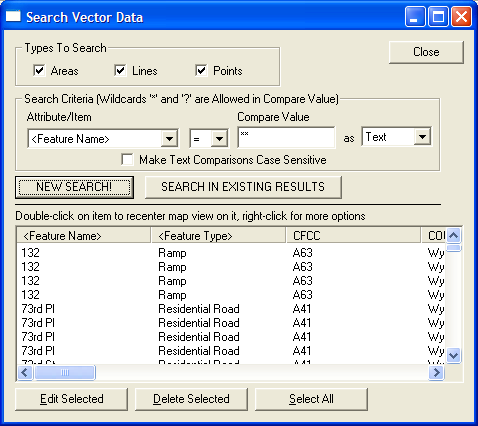
The Search Vector Data dialog displays a list of all of the vector features (areas, lines, and/or points) which match the specified Search Criteria. The Search Criteria can be applied to any attribute value of the loaded features, the display label field, or the description/type field. Comparisons to the Compare Value can be done either textually or numerically. For text equal and not-equal searches, the Compare Value field can contain the ? and * wildcard characters.
In addition, one can control which vector object types (area, line, and/or point) to include in the search.
Once you have your Search Criteria set how you want for the search, press the New Search button to actually perform the search and display the matching results in the results list. The results will be sorted in ascending order by the names of the features by default, but you can click on any column header to sort the results by the values in that column. Clicking the same column header again will reverse the order of the sort. You can also press the Search in Existing Results button to apply the new search criteria to the existing results. Using this you can create complicated searches based on multiple criteria.
Double-clicking on an item in the list will recenter the view on that object.
The Edit Selected button displays a dialog allowing the user to modify the name, feature type, and drawing style of any features selected.
The Delete Selected button will mark all selected features as deleted.
If you right click on the results list, additonal options will appear, such as the option to select all of the results in the list. If multiple line features are selected in the results list, when you right click there will be an option to combine those line features into new line features if the selected lines connect at their endpoints. Options for copying the selected features to the clipboard and selecting the selected search results with the Digitizer Tool for further editing will also appear if any results are selected.
ADVANCED USERS: You can change the default search string from '*' to whatever you want by creating a new registry string value with the desired default search string at "HKEY_CURRENT_USER\Software\Global Mapper\DefaultVectorSearchStr".
Search and ReplaceThe Search and Replace command allows for searching for a particular text string in the attributes and name of loaded features and replacing that with some other text string. When you select the command, the Search and Replace dialog (pictured below) is displayed, allowing you to setup the search-and-replace operation.
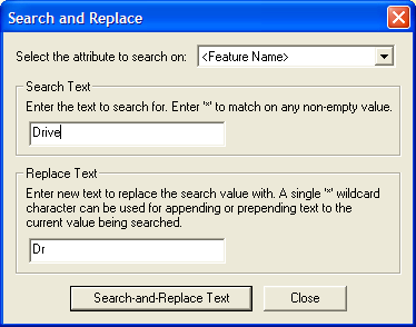
When searching, you can either enter a Search Text value of the string to match on, or you can enter an asterisk (*) to match any non-empty value. In the Replace Text box you have more options. You can specify a simple text string to replace the Search Text with, or you can use a single wildcard to prepend or append text. For example, to prepend the text 'Sample' in front of your search string, enter a replace string of 'Sample*'. To append the text to your search string, use '*Sample'.
Find AddressThe Find Address command displays the Search for an Address in the US dialog (pictured below) which allows searching for an address, city, or zip code in the United States.
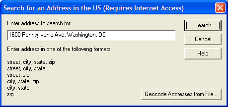
If an address is found that matches the requested location, a results dialog (see sample below) is displayed with the matching location information, as well as button to allow creating a new point feature at the address location, re-centering the map view on the address, and copying the address information to the Windows clipboard for easy pasting into another application.
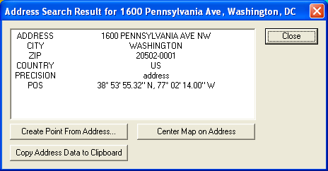
The dialog also includes a Geocode Addresses from File button that allows you to geocode a bunch of addresses at once. The text file that you select to convert can either contain a list of files with addresses in the single line form accepted when searching on a single address, or it can be a comma or tab-delimited file with named columns, like Address, City, State, and Zip (see the example file contents below). Note that you are limited to about 5,000 address searches within a single 24 hour period.
Sequence,Name,Address,City,State,ZIP,Phone
1,McPeak Betty,,North Pole,AK,99705,907-488-4879
2,McPeak P,,Anchorage,AK,99501,907-770-2957
3,McPeak Roger,,North Pole,AK,99705,907-488-8823
4,McPeak Allan,1011 McCay Ave,Mobile,AL,36609,251-633-0931
5,McPeak Bill,395 Dupree Dr,Huntsville,AL,35806,256-837-2657
6,McPeak Carol,5923 Lumsden Battery Cir,Mobile,AL,36619,251-661-0989
7,McPeak Dwight,5548 Heath Row Dr,Birmingham,AL,35242,205-991-8862
8,McPeak Faye,146 Larkin St,New Market,AL,35761,256-379-5416
9,McPeak Faye,395 Dupree Dr,Huntsville,AL,35806,256-837-2657
When batch geo-coding, you can choose to either geocode US addresses against an online database, or to geocode to loaded road data instead. If you choose to geocode against loaded road data, you must already have road data loaded with a known address format, like Tiger/Line data in the US, or data with supported attribute names for addressing information, like R_FROM_ADR, L_TO_ADR, R_FROM_CITY, L_TO_CITY, etc., so that the data can be geocoded.
Once you complete a batch geocode operation, the results are displayed in a list in a dialog (see sample below). The Batch Geocode Results dialog contains buttons allowing you to create new point features from the matched address results or to export the results to a new file.
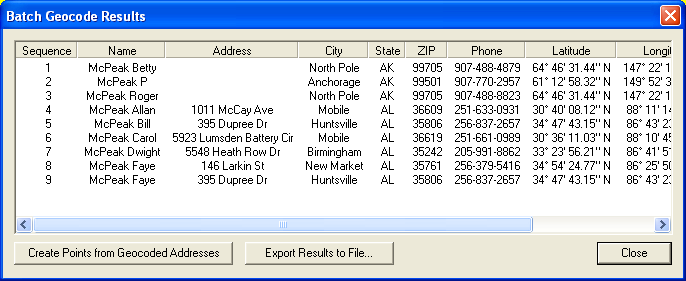
The Find Features with Duplicate Attribute Values command allows you to search loaded vector features to find those that have duplicate values for a selected attribute value. You can then view the results and manually edit them, or choose to automatically assign unique numeric values for the selected attribute so that duplicates no longer exist.
When you select the menu item you are first prompted to select which attribute (including feature name) to search for duplicates on, then the search proceeds and any duplicate values are display in the Duplicate Search Results dialog (picture below). This dialog allow you to view the features with duplicate results and to edit those features or automatically assign new unique values. You can also press the Delete Duplicates button to mark the duplicate features as deleted. When doing this you will have the option to mark all duplicates (except for the first one) as deleted, or to just delete the duplicate features that also have duplicate coordinates (this is what you'll most often want to do).
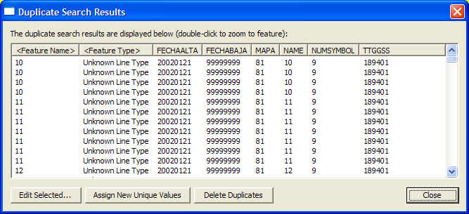
The Help menu offers the following commands:
The Online Help... command open the table of contents for the Global Mapper User's Manual in your browser window. You must be connected to the Internet in order to access the online manual.
FAQ CommandThe FAQ... command opens the Frequently Asked Questions (FAQ) for Global Mapper in your browser window. You must be connected to the Internet in order to access the FAQ.
User's Group CommandThe User's Group command open the Global Mapper Yahoo User's Group in your browser window. You must be connected to the Internet in order to access the user's group.
Register Global Mapper CommandThe Register Global Mapper... command displays the Registration dialog which allows the user to enter their registration name and code they obtained after purchasing a license for Global Mapper.
Check for Updates CommandThe Check for Updates... command checks to see if a newer version of Global Mapper than the current version is being used. If so, a dialog describing the new version is displayed.
Automatically Check for Updates at Startup CommandThe Automatically Check for Updates at Startup... command controls whether or not Global Mapper ever automatically checks for a new version automatically when you start it.
About Global Mapper CommandThe About Global Mapper... command displays the About Global Mapper dialog which contains version and contact information for Global Mapper.