The Image Rectification feature in Global Mapper allows you to load and work with any JPG, PNG, or TIFF imagery, regardless of whether or not spatial positioning information is provided with it.
For example, you could scan in an image of a map to a JPG file, use the File->Rectify Imagery menu command to enter the coordinates of several points on that image, and then load it into Global Mapper, properly overlaid with any other loaded data.
Once you have rectified an image in Global Mapper, you can then export it to any of the supported export formats to obtain a fully rectified image that can then be immediately loaded into numerous other imaging and GIS packages.
If you find that after rectifying a file that you want to modify the rectification, you can simply select the layer in the Overlay Control Center, then right-click and select the Modify Layer Position/Projection option to bring up the rectification dialog for that layer.
As-Needed RectificationThere are two ways to rectify imagery in Global Mapper. The first is to simply load the imagery file needing to be rectified just like any other file. Global Mapper will automatically prompt you to rectify an image if it cannot automatically determine where on the earth the image should be placed.
If you indicate that you would like to rectify an image when prompted, the Image Rectifier dialog will appear, allowing you to enter ground control points for the image in order to rectify it. This process is described in detail later.
Batch RectificationBy using the Rectify (Georeference) Imagery command under the File menu, you can select multiple images to rectify at a time. You will be allowed to rectify all images that you select, regardless of whether they already contain valid positioning information. In this way, you can correct poorly positioned imagery.
Using the Batch Image Rectification Options dialog (pictured below), you can setup whether you would like to view the images after rectification, export them to one of several formats, or both.
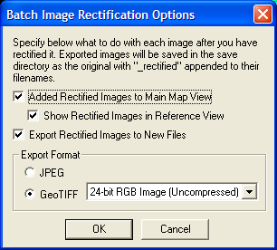
Regardless of which options you select, you will then be allowed to rectify each image in turn using the Image Rectifier dialog, while is described in detail later. As you rectify each image, it will get added to the Reference Images view in the Image Rectifier dialog, allowing you to select ground coordinates from it for subsequent images. This allows you to ensure a good fit between adjacent data files.
If you selected to save the image(s) to JPG or GeoTIFF image(s), the new files will be written after you have rectified ALL of the selected files. This is extremely useful as you can setup the rectification parameters for numerous images, then let the sometimes lengthy rectification and saving process happen while you do something else. All newly rectified files will be created in the same directory as the original images, with _rectified appended just before the file extension. The original imagery will remain intact and unchanged.
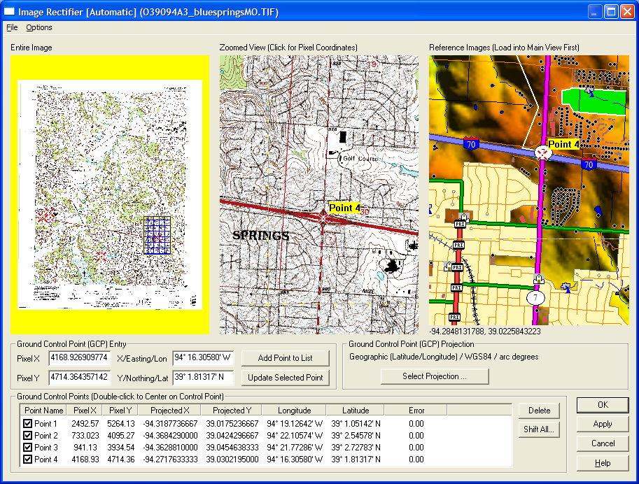
The Image Rectifier dialog is the heart of the image rectification process. This dialog contains everything that you need to rectify an image, from graphical views of the image, to lists of ground control points, to an Options menu for selecting the rectification and resampling methods to use. Each part of this dialog is covered in detail below.
The File menu provides options allowing you to save the current ground control point list to a file and to add additional ground control points from a file. The file specifying the ground control points should be a comma-delimited file in the following format:
<x-pixel location>,<y-pixel location>,<x-ground location>,<y-ground location>,<point name (optional)>,<point error in pixels (optional)>
There are also options on the File menu for loading control points and projection information from an OziExplorer .map, CompeGPS .imp, and Touratech TTQV .cal files as well as saving your control point information to world (TFW, JGW, etc.) files.
The Options menu allows you to setup various options related to the rectification process, as described below:
The Entire Image View portion of the Image Rectifier dialog displays, as you might expect, a view of the entire image being rectified. Any ground control points (GCPs) will also be depicted on this view with a "big red X". The current portion of the image being displayed in the Zoomed View section will be highlighted as well.
You can use the mouse in the Entire Image View to control what portion of the image is visible in the Zoomed View. Clicking the left mouse button anywhere in the Entire Image View will cause the Zoomed View to be recented on the click position. Dragging a rectangle with the left mouse button will cause the Zoomed View to recenter and zoom to the box. If you also hold down the CTRL key when clicking the left mouse button, the Reference Image view will also be recentered on the associated point if there have been enough control points entered to convert the coordinates.
The Zoomed View portion of the Image Rectifier dialog allows the user to pan and zoom around the image as well as select pixel coordinates for control point entry. Any ground control points (GCPs) will be depicted in this view as well with a "big red X".
You can drag a box with the left mouse button to zoom in on a particular area in this view. Right clicking will zoom out. If you hold down the CTRL key when right-clicking will zoom out to the full extents. For those of you with wheel-mice, rolling the wheel forward zooms in and rolling it back zooms out. Moving the mouse near the edge of the Zoomed View displays a pan arrow. Clicking when this is visible will cause the view to pan in the direction of the arrow (hold down CTRL to increase the size of the pan). Pressing down the Shift button while moving the mouse will disable this functionality and allow you to click all the way to the edge of the Zoomed View.
To select a location for control point entry, position the crosshair over the pixel of interest, then press and release the left mouse button. This will cause the pixel coordinates of the point to be entered in the Ground Control Point (GCP) Entry portion of the dialog (described below). In addition, a small red dot will be placed at the click location to make it easy to see. If you also hold down the CTRL key when clicking the left mouse button, the Reference Image view will be recentered on the associated point and the reference coordinates wil automatically be filled in if there have been enough control points entered to convert the coordinates. If you hold down the SHIFT key when left-clicking, the current control point will automatically be added to the GCP list, just as if you had pressed the Add GCP to List button.
The Reference Images portion of the Image Rectifier dialog allows the user to view what is currently loaded in the main Global Mapper view and to enter ground coordinates by left-clicking on an appropriate place on the view. This can be very useful for doing things such as rectifying a satellite photo by clicking on the Zoomed View at a road intersection to select the pixel coordinates, then clicking on the intersection of those roads on a vector file loaded into the main view. By default when you click near a vector feature in the Zoomed View, the location will snap to that vector feature. You can disable this behavior by holding down the ALT key when clicking. If you hold down the SHIFT key when clicking, the clicked coordinates will be rounded to the nearest 30 seconds for arc degree units and the nearest 1000 ground units for other coordinate units. Holding down the CTRL key when clicking the left mouse button will cause the Zoomed Image view will be recentered on the associated point and also fill in the pixel X and Y coordinatess automatically if there have been enough control points entered to convert the coordinates.
You can also zoom and pan the Reference Images view in a manner identical to the Zoomed Images view.
This portion of the dialog is where you actually enter the ground control points (GCPs) that define where the image is on the earth. Typically, you will click a position in the zoomed view to fill in the pixel coordinates, then manually enter the ground coordinates into the X/Easting/Lon and Y/Northing/Lat data fields or else select a point from the Reference Image view for the ground coordinates.
IMPORTANT: If you manually enter the ground coordinates, you must enter them in the coordinate system indicated by the Ground Control Point Projection portion of the dialog, otherwise you will get incorrect results. The one exception is that if you enter a value that looks like a lat/lon coordinates but a projected system is selected, you will be prompted to select whether or not the entered coordinates are lat/lon coordinates or coordinates in the selected projection system.
Once the coordinates are entered, press the Add GCP to List button to add the GCP to the list of GCPs to be used when rectifying the image. The Update Selected GCP button allows you to update the coordinates associated with a previously entered GCP. You can also use Alt+R to simulate pressing the Update Selected GCP button.
This portion of the dialog allows you to select the projection that ground coordinates are entered in as well as what projection the image will be natively treated as when rectified (it can be reprojected later using the normal Global Mapper reprojection mechanisms). See the IMPORTANT note above for more details.
When rectifying new imagery, you can control the default projection used by creating a default_rectification.prj file in your Global Mapper installation folder. If present, the default rectification projection selected when you open the rectification dialog will be whatever projection is specified in that PRJ file.
This section of the dialog contains a list of all of the entered GCPs, including their name, pixel coordinates, ground coordinates, and the estimated error (in pixels) at each GCP based on the current rectification method.
Each GCP has a checkbox next to indicating whether or not that GCP is used for the rectification. This provided you an easy way to remove GCPs from a rectification to see how they affect it.
Double-clicking an item in this list will cause the Zoomed View to recenter on the GCP and will fill in the Ground Control Point Entry section with the pixel and ground coordinates of the selected GCP, allowing for easy updating of GCP locations.
You can move the selection in the GCP list up and down using the Alt+Q and Alt+Z hot keys. These can help facilitate quickly entering lots of GCPs without having to use the mouse.
If you simply want to shift an image, all that you need to do is press the Shift All button and specify the adjustment to apply to each entered GCP.
Once you have entered all of your ground control points (GCPs), press the OK button to complete the image rectification. Depending on how you entered the dialog, the rectified image will now be in the view, will be saved to a new rectified file, or you will start the rectification of the next selected image.
If you are repositioning a loaded file, you can press the Apply button to re-rectify the file with the updated GCPs and see the results of your modifications.