Terrain Analysis Menu
The Terrain Analysis Menu offers the following commands:
The Combine/Compare Terrain Layers command allows the user to generate a new gridded elevation (or other gridded value) layer by combining and/or comparing the elevation values from two other loaded terrain layers.
When selected, the command displays the Combine Terrain Options dialog which allows the user to set up generation of the new terrain layer. Once completed the new terrain layer is added to the Overlay Control Center and displayed.
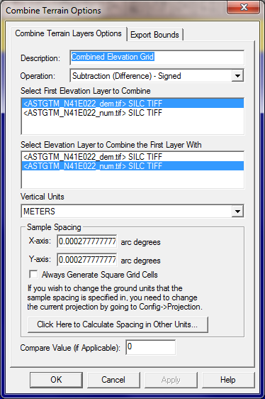
The Combine Terrain Layers Options panel (displayed above) allows the user to select the name to assign to the newly generated layer, select the layers to combine to make the new layer, select the operation to perform when combining the new layer, and select the vertical units and sample spacing of the new layer. The available operations are described below:
Note: Only registered users of Global Mapper are able to combine terrain layers.
The Generate Contours command allows the user to generate equally spaced contour lines from any loaded elevation grid data.
When selected, the command displays the Contour Generation Options dialog (pictured below) which allows the user to set up the contour generation process.
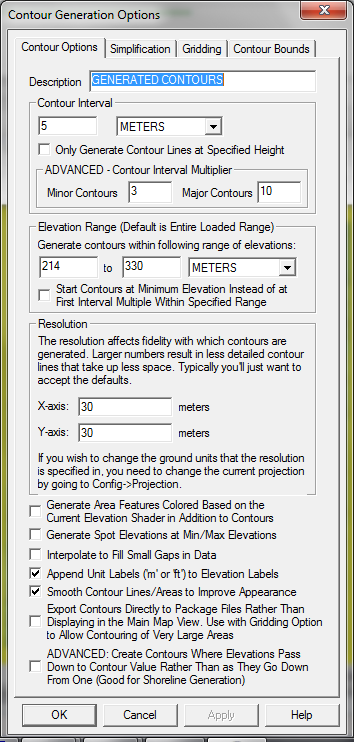
The Contour Options panel (displayed above) allows the user to set the contour interval and units as well as the grid spacing to use when generating the contours. You can also restrict the elevation range within which contour lines are generated (by default all loaded elevation values are considered). In addition, options are available to generate isoheight area features in addition to contour lines as well as spot elevations at the highest and lowest points in the area over which the contours are generated. The smoothing option controls whether or not extra vertices are added along generated line and area features to improve their appearance. If you need to generate a huge amount of contour lines over a large area, the option to export the contours directly to a package file can be used in addition to the Gridding tab options to export those contours directly to package files to get around memory limitations. Note that the contour lines will be generated so that the higher elevations are to the left of the contour line.
The ADVANCED: Create Contours Where Elevations Pass Down to Contour Value Rather Than as They Go Down From One option is an advanced option allowing you to change how the contouring works in flat areas. If this option is checked, you will get contours generated where the terrain surface arrives at a contour height from higher terrain rather than where it departs a contour height for lower terrain. So if you have a flat plain exactly at a contour height you will get the contour at the base of the hill where it starts up rather than at the top where it starts down. This is most useful when you have water (like the ocean) and want to get a shoreline contour generated where the terrain leaves the flat surface of the water.
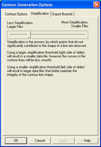
The Simplification panel (displayed below) allows the user to set up the threshold at which points that don't contribute much to the shape of the generated contour are removed in order to generate lines with less vertices. The Gridding panel allows you to break up your contour generation into smaller pieces which can sometimes help reduce memory requirements when generating a very large amount of contour lines. The Export Bounds panel allows the user to set up the portion of the loaded elevation grid data they wish to consider when generating the contours.
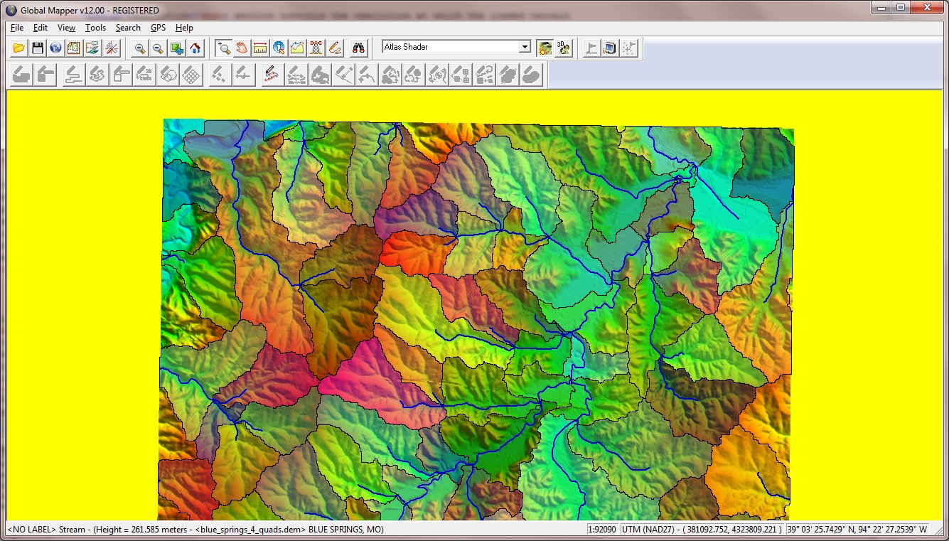
The Generate Watershed command allows the user to perform a watershed analysis on loaded terrain data to find stream paths as well as delineate the watershed areas that drain into a given stream section. The watershed calculation uses the eight-direction pour point algorithm (D-8) to calculate the flow direction at each location, along with a bottom-up approach for determining flow direction through flat areas and a custom algorithm for automatically filling depressions in the terrain data.
When selected, the command displays the Watershed Generation Options dialog (pictured below) which allows the user to set up the watershed generation process.
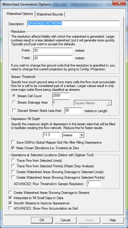
The Resolution section controls the resolution at which the loaded terrain data is sampled to perform the watershed analysis. The default values should capture the full resolution of the loaded terrain data. Larger values (i.e. lower resolution) will cause the calculation to be quicker, but less detailed.
The Stream Threshold section controls how much water must flow to a particular cell before it is considered part of a "stream". Larger values will result in only more water flow areas being delineated, while smaller values will cause more minor water flows to be marked as streams. Each stream segment (i.e. the portion between and inflow and outflow point) can optionally have the area that drains directly to that stream segment marked with a watershed area. Check the Create Watershed Areas Showing Drainage to Streams option to enable creating watershed areas. If you would like to discard any short stream segments that don't have any other streams flowing into them (i.e. short little stub streams feeding into a main trunk), check the option to Discard Stream Starts Less than Some Length. This will remove any short little stream stubs that are below the specified distance threshold (in meters).
Many terrain data sets will contain depressions in the data where flow would terminate unless allowed to fill the depression and spill into the surrounding terrain. The Depression Fill Depth section controls how deep of a depression will be filled before it is considered a basin and flow is allowed to terminate there. The depression fill depth value will automatically be filled in with some guess at a good value based on the range of loaded elevation values, but you might want to modify this, especially if you have relatively flat terrain with a lot of depressions. Note that it can take a while to fill particularly deep depressions. When trying to determine a a good value to use for the depression fill depth you should think about how high of an embankment or 'dam' that you might encounter that you want to allow water to fill up to the top of and pour over, or also how deep of a small pond or puddle to fill and allow spilling out of. You can also check the option to Save DEM to Global Mapper Grid File After Filling Depressions to save the depression-filled terrain to a GMG file so you can load that for future watershed operations to avoid having to fill depressions again.
The Operations at Selected Locations section allows you to perform additional flow and drainage network delineation based on line and point features selected in the Digitizer Tool. The Create Watershed Areas Showing Drainage to Selected Line(s) option will calculate a drainage (watershed) area for each selected line feature showing which portion of the loaded terrain drains to the immediate vicinity (within the specified flow threshold) of the selected line. This is useful to see what drains to something like a road feature. The Create Watershed Areas Showing Drainage to Selected Point(s) option will calculate a drainage (watershed) area for each selected point feature showing which portion of the loaded terrain drains to the immediate vicinity (i.e. within the specified flow threshold of the point location) of the selected point. The Trace Flow from Selected Point(s) (Water Drop Analysis) option will cause a separate arrowed line to be generated starting at each selected point feature showing where a drop of water placed at that point location will flow to. The Trace Flow from Selected Line(s) option will cause an area feature to be generated showing all areas that a particular line feature will drain to. This is useful for determining something like where a leak from a pipeline might leak to.
The screenshot below shows a watershed created from a collection of USGS DEMs. In it you can clearly see the stream network as well as the drainage areas for each stream segment.
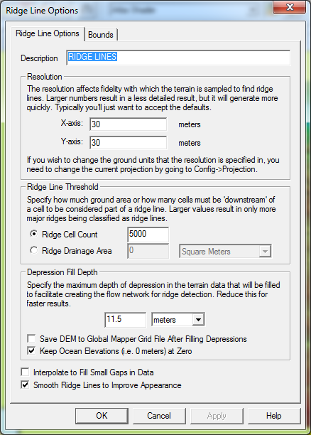
The Find Ridge Lines command allows the user to analyze the loaded terrain data to find significant ridge lines. The ridge line calculation is based heavily on the watershed generation algorithm, so see that for details on how it works. The main difference is that the ridge line operation simply inverts the terrain and where streams of water would form are now the ridge lines in the inverted terrain.
When selected, the command displays the Ridge Line Options Options dialog (pictured below) which allows the user to set up the ridge line determination process.
The Measure Volume Between Surfaces command allows the user to calculate the volume between 2 terrain surfaces. When selected, the command displays a dialog allowing you to select the 2 layers to calculate the volume between as well as the region within which to do the volume calculation.