
The Digitizer Tool allows you to modify existing vector features as well as to create new ones. This tool encompasses a lot of functionality, from modifying the shape and position of area, line, and point features, to editing the attribution and drawing styles of individual vector features. The major activities available with the Digitizer Tool are described below.
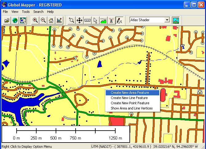
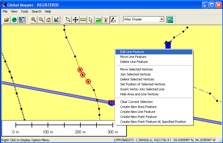
At any time that the Digitizer Tool is active, you have the option to create new area, line, and point features simple by right clicking and selecting either the Create New Area Feature, Create New Line Feature (Vertex or Trace Mode), or Create New Point Feature options on the popup menu (pictured below). Any new features created can be exported to new vector files in any of the supported vector export format (DXF, Shapefile, etc.).
After selecting the Create New Area Feature popup menu option, you can proceed to draw a new area feature with the mouse. To draw the feature, simple left click at each place that you'd like to drop a vertex. To finish the area feature, right click at the desired location of the last vertex to complete the area. You can cancel creation of the new area at any time by pressing the Escape key. Note that while drawing the area you can use the Snapping feature to help align the area with existing features.
Once you've completed drawing the area, the Modify Feature Info dialog will appear allowing you to setup the label, classification, drawing style, and attribution for the area. The perimeter and enclosed area of the area feature will be added as default attributes. The units for these measurements can be modified on the General tab of the Configuration dialog. See Editing Feature Attributes and Drawing Styles for more details.
Once you have completed have completed creating the area, the Digitizer Tool will remain in the area creation mode, so you can simply start left-clicking to draw another area, or right-click to choose a different mode.
You can also create new area features from selected line features by selecting a collection of lines, then right-clicking and selecting the Advanced Feature Creation Options->Create New Area Feature(s) from Selected Line Feature(s) menu command. This will attempt to connect the selected line features to build area features. All line features will be connected as far as possible, then closed to create a new area feature.
After selecting the Create New Line Feature (Vertex Mode) popup menu option, you can proceed to draw a new line feature with the mouse. To draw the feature, simple left click at each place that you'd like to drop a vertex. To finish the line feature, right click at the desired location of the last vertex. You can cancel creation of the new line at any time by pressing the Escape key. Note that while drawing the line in Vertex Mode you can use the Snapping feature to help align the line with existing features.
You can also choose to draw a line using the Create New Line/Area Feature (Trace Mode) popup menu option. To draw the feature, simple press the left button to start the line/area, then trace the path to draw using your mouse while keeping the left button pressed. To finish the feature, simply release the left button. You can cancel creation of the new feature at any time by pressing the Escape key or just releasing the left button then pressing Cancel on the dialog that appears. If you are using a digitizing table just select this mode, then press down the pen to start, trace the path, then release it to end. If your drawn path is nearly closed, you will be asked whether to create a closed area feature from the path or just keep it as a line feature.
Once you've completed drawing the line, the Modify Feature Info dialog will appear allowing you to setup the label, classification, drawing style, and attribution for the line. The length of the line feature will be added as a default attribute. The units for the length measurement can be modified on the General tab of the Configuration dialog. See Editing Feature Attributes and Drawing Styles for more details.
Once you have completed have completed creating the line, the Digitizer Tool will remain in the line creation mode, so you can simply start left-clicking to draw another line, or right-click to choose a different mode.
You can also create new line features from selected area features by selecting one or more areas, then right-clicking and selecting the Advanced Feature Creation Options->Create New Line Feature(s) from Selected Area Feature(s) menu command. This will create a single closed line feature from each selected area feature.
After selecting the Create New Line with Dist/Bearing/COGO popup menu option, you can proceed to select the starting location of the new line feature by left clicking at the desired start location. Note that while selecting the start point for the line you can use the Snapping feature to help align the line with existing features.
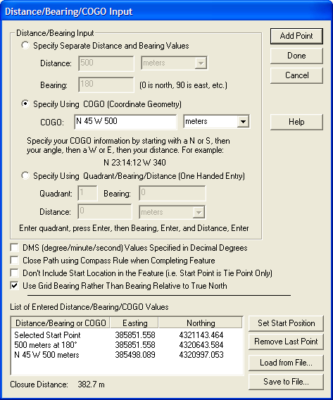
After selecting the starting location, the Distance/Bearing/COGO Input dialog (pictured below) will display, allowing you to enter distance/bearing information for additional points either as separate distance/bearing values, as a COGO (Coordinate Geometry) coordinates (see below for explanation), or as a quadrant/bearing/distance value. Once you have entered all of your points, press Done to complete the process and create the new line feature.
You can also check the option to Close Path Using Compass Rule when Completing Feature. If this option is checked, all of the points will be adjusted using the compass rule to ensure that the shape is closed. The compass rule evenly distributes the shift required to close the shape to all vertices and is commonly used by surveyors.
You can achieve very fast entry of large collections of distance/bearing of quadrant/distance/bearing values by simply using the number pad and pressing Enter after each value. This will take you to the next field and finally add the point when you press Enter on the last field. This will also take you back to the first field to allow continuously adding points with only one hand, keeping your other hand free to mark your place on the list of values.
Notes on BearingsWhen entering data using the Specify Separate Distance and Bearing Values option, the bearing values are degrees clockwise from true north, so 0 degrees is north, 90 degrees is east, etc. For the Specify Using Quadrant/Bearing/Distance option, you specify a quadrant value of 1 to 4, with 1 being the NE quadrant, 2 being the SE quadrant, 3 being the SW quadrant, and 4 being the NW quadrant. The bearing values are then east of the NS line for quadrants 1 and 2 and west of the NS line for quadrants 3 and 4.
It is also important to remember that any bearing are specified relative to true north (unless you check the Use Grid Bearings Rather Than Bearing Relative to True North), so if your projection isn't oriented so that straight up is true north (most projected systems, like UTM, are not unless you are right at the projection center) a line of bearing 0 won't be straight up, but will be slightly skewed so that it points at the North Pole. A line of bearing 0 will be straight up in projections like Geographic or Mercator where true north is always straight up.
If you check the DMS (degree/minute/second) Values Specified in Decimal Degrees option, you can enter your DM (degree/minute) or DMS (degree/minute/second) values as decimal degrees. For example with this option checked, a value of 40.3020 is interpreted as 40 degrees, 30 minutes, and 20 seconds. The basic format of degree fields when this option is checked is DD.MMSS.
Example COGO InputN 23:14:12 W 340 S 04:18:56 E 230
The first character of a COGO input string must be either the character 'N' or 'S' to indicate whether the bearing is relative to the north or south directions. After another space, the angle begins. The angle can be in any angle specification that Global Mapper supports, including degrees, degrees/minutes, or degrees/minutes/seconds. A space follows the angle, and is then followed by either the 'E' or 'W' characters. A space separates the bearing from the distance (which should be in appropriate linear units).
For those unfamiliar with the notation for bearings: Picture yourself in the center of a circle. The first hemispere notation tells you whether you should face north or south. Then you read the angle and either turn that many degrees to the east or west, depending on the second hemisphere notation. Finally, you move distance units in that direction to get to the next station.
After selecting the Create New Point Feature popup menu option, you can proceed place the point feature by left clicking at the desired location of the point. You can cancel creation of the new point at any time by pressing the Escape key.
You can also use the Create New Point Feature at Specified Position option to create a new point feature at a manually specified location. When you select this option, a dialog appears allowing you to enter the location for the new point feature in either latitude/longitude coordinates or coordinates in the current view projection.
Once you've placed the point, the Modify Feature Info dialog will appear allowing you to setup the label, classification, drawing style, and attribution for the new point feature. See Editing Feature Attributes and Drawing Styles for more details.
Once you have completed have completed creating the point feature, the Digitizer Tool will remain in the point creation mode, so you can simply left-click to place another point, or right-click to choose a different mode.
You can also create new point features from the centroids of selected area features or from the vertices of selected line and area features by selecting one or more areas or lines, then right-clicking and selecting the appropriate option under the Advanced Feature Creation Options menu.
After selecting the Create Range Ring(s) popup menu option, you can proceed to place the center location of your range rings by left clicking at the desired location. If you had point features selected when you selected this option you can also choose to create the rings centered on the selected point feature(s) rather than manually specifying a center location. You can cancel creation of the range ring(s) at any time by pressing the Escape key or right clicking.
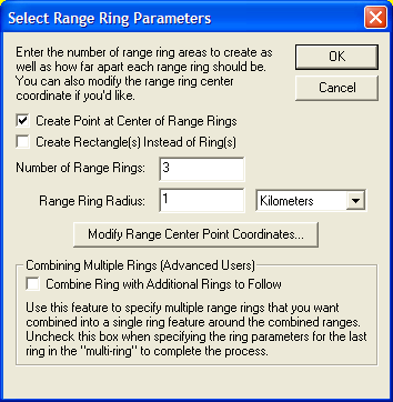
After selecting the center of your range ring(s), the Select Range Ring Parameters dialog (pictured below) appears and allows you to setup how many range rings you would like to create and how far apart you would like to create them. You can choose to create rectangles with the specified range as the radius rather than a ring if you would like. You can also choose to create a "multi-ring". Checking this box will delay the actual range ring creation until you have added additional range rings and unchecked the box. Then all rings in the "multi-ring" will be combined if possible to build nice looking combined range rings.
Once you have completed have completed creating the range ring(s), the Digitizer Tool will remain in the range ring creation mode, so you can simply left-click to create additional range rings centered on another location, or right-click to choose a different mode.
The range ring feature has numerous applications, including search-and-rescue and aviation.
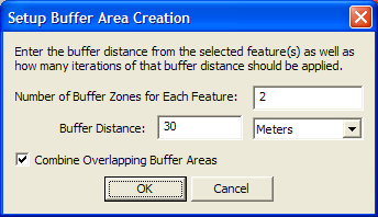
After selecting the Create Buffer Areas Around Selected Feature(s) option in the Advanced Feature Creation popup menu, the Setup Buffer Areas dialog (pictured below) appears and allows you to setup how many buffer areas that you want to create around each selected feature and at what distance to space them. For example, if you want to create buffers at distances of 100, 200, and 300 meters around each selected feature, you would specify that you want to create 3 buffer areas with a buffer distance of 100 meters. If you would like to combine all overlapping buffers into larger combined areas, simply check the option to Combine Overlapping Buffer Areas. To create buffers some distance inside a selected area feature rather than outside of it, simply specify a negative buffer distance.
Once you have completed have completed creating the buffer areas(s), the newly created areas will automatically be selected so you can easily right-click to edit them, display measurement information, etc.
Under the Create Area Shapes and Create Line Shapes right-click popup menus you will find options to create Arc, Circular, Elliptical, Rectangular, and Square area and line features. For all of these shape types (except the rectangular/square option where you manually enter the coordinates), you click and hold the left mouse button at the center of the feature, then drag it until it is of the desired shape. For Circular/Elliptical features and Arcs, the default shape follows a circle and holding down the SHIFT key will dragging will result in an ellipse. For Rectangular/Square features, the default shape is a rectangle and holding down the SHIFT key will force the dragged shape to be square. If you hold down the 'T' key when left clicking to start the shape, the start point will be treated as the top left corner of the feature rather than the center of the shape feature.
Once the shape is to your liking, release the left mouse button and the Modify Feature Info dialog will appear allowing you to setup the label, classification, drawing style, and attribution for the new feature. See Editing Feature Attributes and Drawing Styles for more details.
Once you have completed have completed creating the shape, the Digitizer Tool will remain in the selected shape creation mode, so you can simply start drawing a new shape, or right-click to choose a different mode.
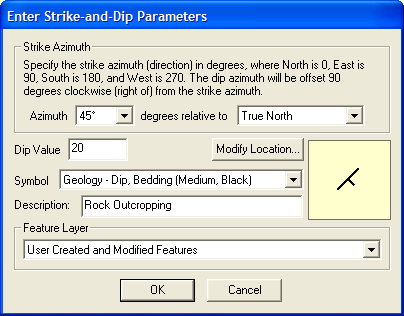
After selecting the Create Strike-and-Dip Point popup menu option, you can proceed to select the location of your new point by left clicking at the desired location. You can cancel creation of the point(s) at any time by pressing the Escape key or right clicking.
After selecting the locationof your strike-and-dip point, the Enter Strike-and-Dip Parameters dialog (pictured below) appears and allows you to setup your point. This includes selected the azimuth angle for your strike, either relative to True North (the default) or to the top of the map screen, the dip value for your point (which will be used as the display label on the map), the symbol to use, an optional description, and which layer in the Control Center to place the new point feature. There is also a Modify Location button which allows you to fine-tune the location of the point by manually entering coordinates.
Once you have completed have completed creating the strike-and-dip point, the Digitizer Tool will remain in the strike-and-dip creation mode, so you can simply left-click to create additional points centered on another location, or right-click to choose a different mode. If you hold down the Ctrl key when left-clicking to create additional points the new strike-and-dip point will automatically be created at the clicked location using the same parameters as the last strike-and-dip point that was created, allowing you to quickly place a lot of points without going through the dialog each time.
You can create new point features evenly spaced along a selected area and line features by right clicking and selecting the Advanced Feature Creation submenu option Create Point Features Spaced Along Selected Feature(s). This will present a dialog allowing you to specify the spacing to use, then create new point features at the specified interval along the line.
In addition to creating new vector features, the Digitizer Tool is also very useful for editing existing vector features. This tool provides the ability to move, delete, and reshape vector features, as well as modify the label, classification, drawing style, and attribution of any vector feature loading from any file format supported by Global Mapper. Note than any edits made are NOT automatically saved back to the origin file, but they will be saved in Global Mapper workspaces and into any exported vector files.
Before you can edit an existing feature or features, you first must select them. Once a feature is selected, you can tell that it is selected because it will be drawn with a different style. The different methods for actually selecting features are described below.
One way to select features is by simply by clicking the left mouse button near the feature, or in the case of area features, within the feature. Using this method, the closest point or line feature will be selected, or if no point or line features are nearby and you clicked within an area feature, the area feature will be selected.
To select multiple features at a time, you can drag a selection box by holding down the left mouse button to draw a box. Any features entirely within the box drawn or features which are cut by the box will be selected. If you hold down the 'I' key while dragging the box, only features and vertices that are completely within the box will be selected. This is useful for things like selecting a point feature that is on top of a line/area border.
You can add to an existing selection by holding down the CTRL key while performing a selection with any of the above described methods. You can deselect features by holding down the SHIFT key while performing a selection. You can toggle the selection state of features by holding down both the SHIFT and CTRL keys while performing a selection. As a final option, holding the 'P' key when clicking to select the feature may be used to select the topmost area feature at a location. This is useful for selecting area features that may be overlaid by a line or point feature. It's functionally equivalent to using the Vector Display tab of the Configuration dialog to enable only the "Select From Areas" option - a temporary selection filter.
If you are planning on moving lots of features, you can speed up the process by holding down the ALT key when selected features and/or vertices. Doing this will cause you to automatically put into move mode when selecting new features and/or vertices.
You can also select area, line, and point features within selected area features by first selecting one or more area features using the previously described methods, then right clicking and selecting the appropriate option under the Advanced Selection Options submenu. This makes it easy to find and edit all of the point, line, and/or area features within some other area feature(s).
When working with island and parent areas, there are also some options available under the Advanced Selection Options submenu that make it easy to select all of the island areas associated with selected parent areas and to also deselect the parent area for a selected island area.
If the Show Area and Line Vertices option is enabled (Shift+V is a keyboard shortcut to toggle this setting), you can also select individual vertices on area and line features. You must select vertices before options allowing you to work with individual vertices in area and line features appear in the right-click options menu. Selected vertices will be shown on the display with a circle around them.
To select vertices, simple left click near a vertex to select the closest one if any are nearby, or drag a box to select all vertices within the box. The same behavior modifications occur as described above if the CTRL and/or SHIFT keys are pressed when selecting. If you hold down the 'S' key when left clicking, only vertices from already selected lines or areas will be considered.
Pictured below is a screen capture showing a line feature and several of its vertices selected, with a right-click popup menu opened to show the available options.
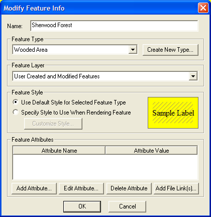
When a single area, line, or point feature is selected, there is an option on the right-click popup menu allowing you to edit that feature (i.e. Edit Area Feature, Edit Line Feature, or Edit Point Feature). Selecting that option displays the Modify Feature Info dialog which allows you to modify the Name, Feature Type, Drawing Style, and Attributes for the selected feature. You can also access this dialog by double-clicking on a feature. A sample of this dialog for an area feature is below.
The Name field allows you to modify the display name of the feature. If you are editing or creating a road feature, you can set the name to a commonly supported iconized road name (like I-35 or US40) and when you press OK you will be prompted whether or not to display an icon for the road name. This allows you to generate a nice iconized display for most highway types. If you would like to split point and area labels up onto multiple display lines, you can add the newline escape sequence (\n) to your display label. You will then be prompted to split your label onto multiple lines when you save the changes.
If editing an area or line feature, the Vertices button will appear allowing you to edit the vertices of the selected feature, including working with per-vertex elevations for 3D features.
The Feature Type selection allows you to choose which Global Mapper classification to assign to the feature. You can also choose to create a new Global Mapper type with the Create New Type button.
The Feature Layer selection allows you to choose which layer that the feature should be assigned to. You can choose an existing layer, the User Created and Modified Features layer, or you can create an entirely new layer to add the feature to. A layer corresponds to a single entry in the Control Center.
The Feature Style section allows you to modify the drawing style of the selected feature. Selecting the Use Default Style for Selected Feature Type option will cause the currently configured style for the Feature Type from the Area, Line, or Point Styles tab of the Configuration dialog to be used when rendering the feature. Alternatively, you can choose the Specify Style to Use When Rendering Feature option and select how you want this feature drawn, independent of the selected Feature Type.
The Feature Attributes selection allows you to edit the attributes that are associated with this feature. The Add File Link(s)... button in this section allows you to easily add attributes that point to files somewhere on disk without having to manually type in the file name. These file links can later be followed from the Feature Information dialog displayed with the Feature Info tool.
When more than one area, line, and/or point feature is selected, there is an option on the right-click popup menu allowing you to edit the selected features. Selecting that option displays a dialog dialog which allows you to modify the Name, Feature Type, Feature Layer, and Drawing Style, and Attributes for the selected features.
Removing an unwanted feature is quite simple. All that you need to do is select the feature(s) that you wish to delete, then either select the Delete option from the right-click popup menu or press the DELETE key. Once you've done that, the feature is marked for deleted and will no longer appear on the display unless the Render Deleted Features option is enabled on the Vector Options tab of the Configuration dialog.
If you decide that you didn't want to delete a feature, simple enable the Render Deleted Features option (see above) to show the deleted features, then select the deleted features and select the Undelete Feature(s) option from the right-click popup menu.
You can move area, line, and point features simply by selecting the feature(s) that you wish to move, then selecting the Move XXX Feature(s) option from the right-click popup menu, or you can simply hold down the ALT key when selecting the feature(s) to move to automatically enter move mode for the selected feature(s)/vertices. Once you've done that, simply hold down the left mouse button and drag the features to the desired new location.
If you'd only like to move the selected feature(s) either horizontally or vertically, you can hold down either the 'X' or 'Y' keys on the keyboard to restrict the movement to that axis. Holding down both keys will move the feature(s) diagonally.
If after moving a feature you decide that you want to undo the move, simply select the feature(s) that you want moved back and select the Restore Original Shape from the right-click popup menu.
If you need to shift/offset selected features a particular distance, you can also simply right click when the feature(s) to move are selected and select the Shift/Offset Selected Feature(s) option. This will bring up a dialog allowing you to specify a distance to shift the selected features by in both the X and Y direction or some distance along a specified bearing.
You can change the shape of area and line features in several different ways. You'll first have to enable the Show Area and Line Vertices option (Shift+V is a keyboard shortcut to toggle this setting) before having access to the features described below. You'll also need to select the vertices to work with before performing any of the described operations except inserting new vertices.
The following options are available for reshaping area and line features:
If after modifying the shape of an area or line feature you decide that you want to undo the changes and restore the feature to its original shape, simply select the feature(s) that you want restored and select the Restore Original Shape from the right-click popup menu.
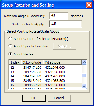
When you have one or more features selected, you can right click and select the Rotate/Scale Selected Features command to bring up the Setup Rotation and Scaling dialog (pictured below). This dialog will allow you to rotate and scale the selected features about a point that you select.
You can combine overlapping or adjacent area features into a single area feature by first selecting the area features to combine, then selecting the Combine Selected Area Features right-click menu option. Any areas that are succesfully joined into a new one will be marked as deleted.
You can combine multiple line features into a single line feature by first selecting the line features to combine, then selecting the Combine Selected Line Features right-click menu option. This option will connect any lines that you have selected that join at an endpoint. Any lines that are succesfully joined into a new one will be marked as deleted.
You can find the intersection of two area features by selecting both features, then right clicking and selecting the Find Intersection of Selected Area Features menu command. This operation will create a new area feature from the intersection of the two selected area features. You will also be prompted to create new area features from what is left outside of the intersection. If you choose this option then the original area features will be marked as deleted once the operation completes successfully.
You can cut one area feature shape out of another area shape, either adjusting the second areas outer boundary or making the first area feature become an island, or hole, within the second area by first selecting the area(s) that you want to cut from another area/make into an island, then right click and select the Cut Selected Area(s) from Another Area (Add Islands) menu option. You will then need to left-click in the area feature that you would like to cut the selected area(s) out of.
You can split an existing area feature into two new area features by selecting the two vertices across which you would like to split the area, then right clicking and selecting the Split Selected Area at Selected Vertices menu option. This will generate two new area features by splitting the selected area feature across the segment between the two selected vertices. Note in some situations you will get invalid areas or no result at all, so be careful to select vertices for which the connected segment does not cross outside of the area or intersect any island areas.
You can crop or split selected line features to a selected area feature by right-clicking and selecting the option to Crop/Split Selected Lines to Selected Areas. This will delete any portion of the line feature that lies outside of the selected areas unless you select the Split option, in which case separate lines will be created for the parts inside and outside the selected area feature(s). Note that the original line will remain available as a deleted feature, so you can recover the original line if needed.
Occasionally you may wish to make copies of existing features or perhaps move features from one instance of Global Mapper to another. You can easily do this by first selecting the features, then either making a copy of those features (use Edit->Copy Selected Features to Clipboard menu command or Ctrl+C shortcut) or cutting those features to the clipboard (use Edit->Cut Selected Features to Clipboard menu command or Ctrl+X shortcut). Then, simply paste those features into any running instance of Global Mapper using either the Edit->Paste Features from Clipboard [Ctrl+V shortcut] or Edit->Paste Features from Clipboard (Keep Copy) [Ctrl+Shift+V shortcut], the latter of which keeps the features on the clipboard for additional pasting rather than wiping the clipboard clearn.
During some operations (i.e. drawing new area or line features or graphically placing a new point feature), the cursor can automatically snap to existing features when you move it near them to facilitate lining up features. This happens by default unless the ALT or V keys are depressed. Pressing the ALT key causes no automatic snapping to occur, while pressing the V key causes only vertices on existing features to be snapped to. Holding down the P key causes only nearby point features to be snapped to.
Note that you can reverse the automatic snapping behavior so that snapping is disabled by default and holding down the ALT key enables snapping on the Vector Display tab of the Configuration dialog.
ADVANCED USERS: You can customize the pixel radius used when looking for a location on existing features to snap to using the DWORD registry key 'HKEY_CURRENT_USER\Software\Global Mapper\SnapToPixelRadius'. The default value is 10 pixels. Just create that registry key and provide the distance (in pixels) to search from the cursor location for a location to snap to.
When drawing new area or line features or moving existing features, you can use the CTRL and SHIFT keys to cause the next vertex to be snapped vertically or horizontally relative to the last vertex or moved vertically or horiztonally compared to the features current location. Hold down the CTRL key to snap vertically, the SHIFT key to snap horizontally, or both the CTRL and SHIFT keys to snap diagonally.
During some operations, like drawing new features, you can undo your last placed point by pressing Ctrl+Z.
Depending on what types of feature are selected and what data is available, additional options may appear on the option menu that appears when right clicking. These additional options are described below.
Adding Elevation Values from Terrain to Point FeaturesIf gridded elevation data (i.e. DEMs) is loaded and one or more point features is selected, the Apply Elevations from Terrain Layers to Selected Point Features option will appear on the right-click option menu. Selecting this option will add an ELEVATION attribute to each selected point feature containing the elevation value at each point location from the top-most terrain layer at that location.
If gridded elevation data (i.e. DEMs) is loaded, the Generate Path Profile From Line option will appear when a single line or area feature is selected. Selecting this option will display the Path Profile/Line of Sight dialog with a 3D path profile of the elevations under the path that the selected feature follows. In addition, if the selected line/area is a 3D feature with per-vertex elevations, those elevations will be displayed as a separate line on the path profile.
If gridded elevation data (i.e. DEMs) is loaded and at least one area or line feature is selected, the Calculate Elevation/Slope Stats for Selected Area/Line(s)... option will appear when right clicking. Selecting this option will examine the loaded terrain within the selected area feature(s) and, if terrain is found within a selected area, add MIN_ELEV, MAX_ELEV, AVG_ELEV, STD_DEV_ELEV, MAX_SLOPE, AVG_SLOPE, and STD_DEV_SLOPE attributes to the area containing the minimum, maximum, average, and standard deviation of elevation values encountered within the area feature as well as the maximum, average, and standard deviation of the slope values (in degrees) found within the area. For selected line features, the maximum and average slope (in degrees) for the line will be computed add added as MAX_SLOPE and AVG_SLOPE attributes.
If you have a single area or line feature selected, the Measure Volume option will appear when bringing up the right-click menu. Selecting this option will allow you to calculate cut-and-fill volumes either within the selected area or along the selected line feature. For more information about this operation, see the cut-and-fill section of the Measure Tool help.
If one or more area and/or line features are selected, the Add/Update the Measure Attributes of Selected Feature(s) option will appear when right clicking. Selecting this option will add measurement attributes to the selected features that do not already have them, or update the measurement attributes of features that do. The measure attributes include LENGTH for lines and PERIMETER and ENCLOSED_AREA for areas.
In addition to adding/updating the measure attributes for the selected feature(s), the combined length and/or enclosed area of the selected line and area features will also be reported by this command.
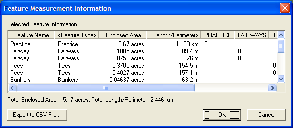
You can also select the Display Feature Measurements option to display a dialog (pictured below) listed the measurements and attributes of each selected line and area feature as well as the total combined enclosed area and perimeter/length of the features. This dialog also allows you to easily export the results to a CSV file.
If two of more line features are selected, the Insert Vertices at Intersections of Selected Features option will appear when right-clicking. Selecting this option will find all intersections between selected line features and insert new vertices in the selected lines at the intersection locations if there are not already vertices at the intersection. Once the operation is complete you will also be prompted as to whether or not you want to split the selected lines at the locations where intersections were found.
This is a very powerful command allowing you to make a line network have node-to-node connectivity and even make sure that lines terminate at intersections if required for your application. This is commonly used for making routable street maps.
If two of more line features are selected, the Find Non-Connected Line Endpoints option will appear when right-clicking. Selecting this will display a dialog allowing you to either mark all line endpoints that do not connect to an endpoint (not an interior vertex) of another selected line or those line endpoints that don't connect and are within some distance of another selected line endpoint. This is a very useful feature for allowing easy identification and fixing of connectivity issues within loaded vector data.
Any line endpoints that do not connect based on the selected criteria will be displayed with a blue circle over that endpoint. Once you think you have fixed the connectivity issues at a location, simply re-run the command to find the non-connected line endpoints to update the display of the blue circles (they are not automatically updated as you join line endpoints).
If two of more point features are selected, the Find Selected Points Within ??? Meters of Other Selected Points option will appear when right-clicking. Selecting this will display a dialog allowing you to specify a search distance. Any selected point features that are within the specified search distance of another selected point feature will be displayed with a blue circle over that point. If you delete or move some points to remove duplicates (the primary use of this tool), simply re-run the command to find the to update the display of the blue circles (they are not automatically updated as you edit the data).
If one or more area features are selected, the Advanced Feature Creation Options->Create/Flatten Terrain from Selected Area Feature(s) option will appear when right-clicking. Selecting this option will allow you to create a new elevation grid covering the selected area features that has all points within the selected area feature(s) set to the elevation of those area features. Any portions of the new elevation grid outside of the area features will be set to invalid, allowing any underlying terrain to show through. If you also select the option that elevations are relative to the height of any underlying terrain, the new terrain surface will have heights equal to the original height of the terrain at each sample location within the area offset by the elevation value of the area feature. This functionality is useful for adjusting all elevation values within an area by some amount (the area elevation).
This feature provides a very easy way to do things like flatten an area, like a lake, in underlying terrain layers. Just assign an ELEVATION attribute to your area feature, then select it and choose this option to flatten everything inside that area to the elevation attribute value. This is also a nice way to create an elevation grid representing a city-scape from building outlines with ELEVATION attributes.
If one or more point features are selected, the Add Address Information from Roads to Selected Point(s) option will appear when right-clicking. Selecting this option will cause each point to be examined to find the nearest line feature, and, if it contains addressing information, for the address of the nearest point on the line to the point feature to be stored as address attributes with the point feature. A dialog will appear to prompt you for how far from each point that you want to search for a line feature with addressing information.
The following attribute names for line features are recognized as containing address information:
Only the start and end address number are absolutely required for the side of a road to have addressing, in addition to the road having a name.
If one or more point features are selected, the Add Coordinate Attributes to Selected Point(s) option will appear when right-clicking. Selecting this option will cause X and Y attributes to be added (or updated if they already exist) to the selected points with the value being the coordinates of the points in the current projection system.
There are multiple ways to assign attributes to features from other features. This includes, applying attributes to areas from points in those areas, applying attributes to points from the area they are in, and applying attributes to lines from area features they are in. Each of these options is further described below.
If one or more area features are selected, the Add Attributes to Selected Areas from Points option will appear when right-clicking. Selecting this option will cause Global Mapper to search for any point features within each area and, if found, add the attributes from the included point feature to the area's attribute list. If multiple points are found within the area the user is prompted whether or not to use the attribute data.
If one or more point features are selected, the Add Attributes to Selected Points from Areas option will appear when right-clicking. Selecting this option will cause Global Mapper to search for the top-most area feature with attributes that each point feature is in and, if found, add the attributes from that area to the point's attribute list.
If one or more line features are selected, the Add Attributes to Selected Lines from Areas option will appear when right-clicking. Selecting this option will cause Global Mapper to search for the top-most area feature with attributes that each line feature is in and, if found, add the attributes from that area to the line's attribute list.