The 3D View command in Global Mapper allows registered users to view gridded elevation data and any overlying raster or vector data in a true perspective 3D manner. In addition, any vector data with associated elevation values can also be displayed in true 3D.
When selected, the 3D View command displays a window containing a 3D view of the data in the current Global Mapper view. Any imagery or vector data being drawn on top of the elevation grid(s) in the main Global Mapper view will automatically be draped on top of the elevation data in the 3D View window. If so configured, any 3D vector data will be displayed in space as well.
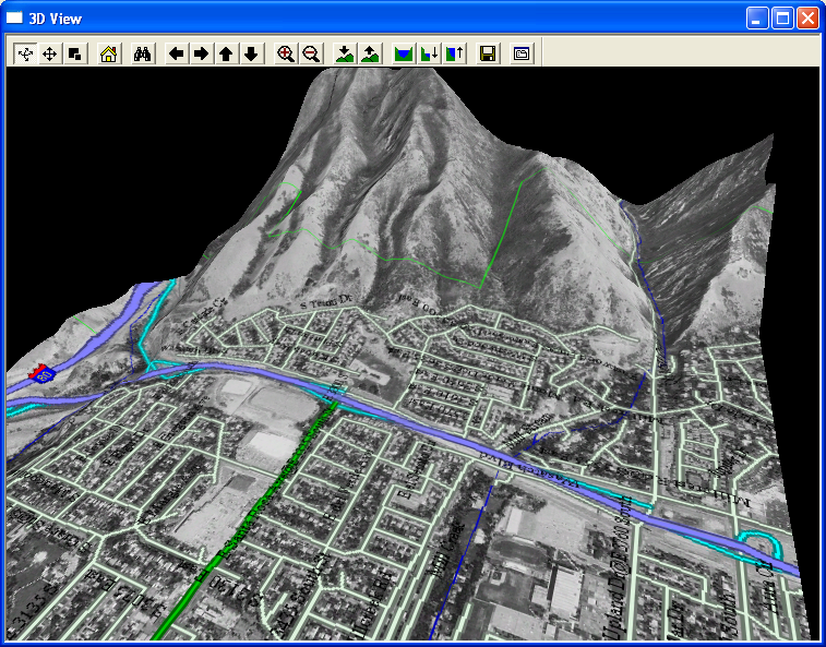
The image below depicts a sample of the 3D View window displayed using 250K USGS DEM data for Salt Lake City, UT overlaid with DOQ satellite imagery from the TerraServer import command under the File menu.
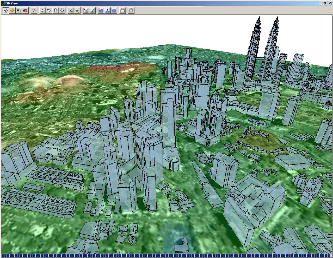
The image below depicts a sample of the 3D View window displaying terrain data with 3D building areas for Kuala Lumpur, Malaysia.
The 3D View window contains a toolbar with command buttons allowing you to modify the default view. You can use the mouse to rotate the view around as well as zoom in. The arrow keys on the toolbar allow you to pan the data visible in the 3D view in any direction. The zoom in and out buttons allow you to zoom in or out on the center of the 3D view. Additional buttons are also available for modifying the vertical exaggeration, displaying water, and saving the 3D view contents to a Windows BMP, TIFF, PNG, or JPG file.
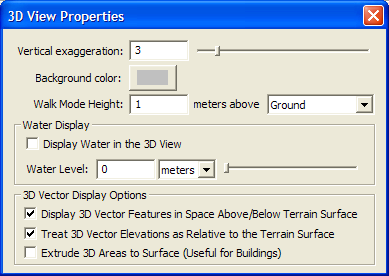
If you press the Change Display Properties button on the 3D toolbar the 3D View Properties dialog is displayed allowing you to configure the 3D view settings, including the vertical exaggeration, the water display, background color, and 3D vector display.
The contents of the 3D View window will always reflect what is visible in the main Global Mapper view. This means that as you pan and zoom around the main Global Mapper view, the contents of the 3D View window will pan and zoom around as well. The reverse is also true in that the pan and zoom buttons on the 3D View window will cause the main Global Mapper view to pan and zoom as well.
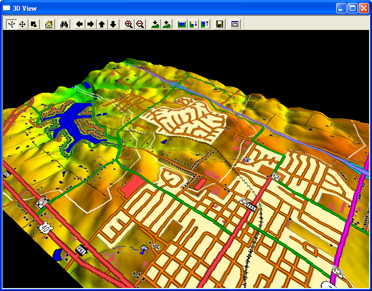
Another example of the 3D view is displayed below. This time, it is several 24K USGS DLGs for Blue Springs, MO overlaid on several 24K USGS DEMs for the same area.
3D vector data is exaggerated along with the terrain so it will align correctly. A bridge going over a gorge with heights of 100m and 110m on either end wouldn't match up with the terrain heights of 100m and 110m if both weren't exaggerated. If relative elevations of 0m and 10m are used, those would end up as 0m and 30m which would still allow the bridge to match up (NOTE: these values assume a vertical exaggeration value of 3.0).
When extruding to the surface, the default base of the extrusion is set just below the minimum elevation, so your extruded areas should always extend through the terrain surface.
You can provide additional control over how 3D vector features are rendered by provided attributes for those features. The supported attributes are as follows: